


Manual (peer-to-peer) WAN optimization configuration
In a manual (peer to peer) configuration the WAN optimization tunnel can be set up between one client-side FortiGate unit and one server-side FortiGate unit. The peer ID of the server-side FortiGate unit is added to the client-side WAN optimization policy. When the client-side FortiGate unit initiates a tunnel with the server-side FortiGate unit, the packets that initiate the tunnel include information that allows the server-side FortiGate unit to determine that it is a manual tunnel request. The server-side FortiGate unit does not require a WAN optimization profile; you just need to add the client peer host ID and IP address to the server-side FortiGate unit peer list and from the CLI an explicit proxy policy to accept WAN optimization tunnel connections.
In a manual WAN optimization configuration, you create a manual WAN optimization security policy on the client-side FortiGate unit. To do this you must use the CLI to set wanopt-detection to off and to add the peer host ID of the server-side FortiGate unit to the WAN optimization security policy.
Network topology and assumptions
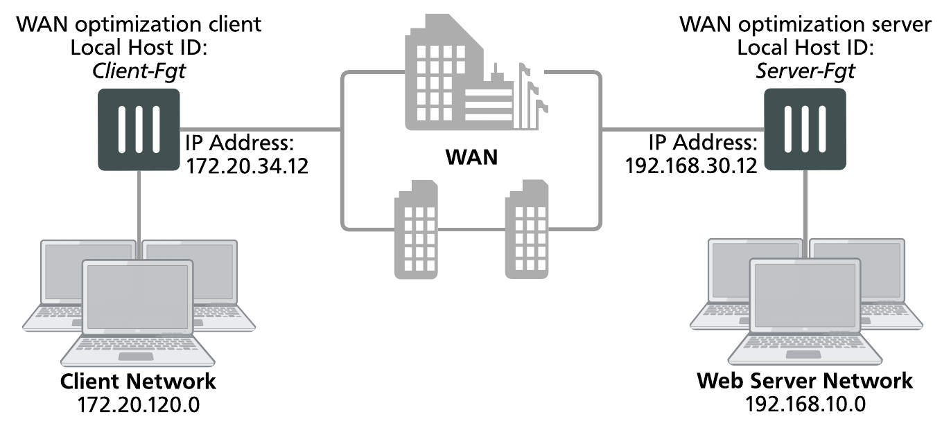
This example configuration includes a client-side FortiGate unit called Client-Fgt with a WAN IP address of 172.20.34.12. This unit is in front of a network with IP address 172.20.120.0. The server-side FortiGate unit is called Server_Fgt with a WAN IP address of 192.168.30.12. This unit is in front of a web server network with IP address 192.168.10.0.
This example customizes the default WAN optimization profile on the client-side FortiGate unit and adds it to the WAN optimization policy. You can also create a new WAN optimization profile.
Example manual (peer-to-peer) topology
General configuration steps
This section breaks down the configuration for this example into smaller procedures. For best results, follow the procedures in the order given:
- Configure the client-side FortiGate unit:
- Add peers.
- Configure the default WAN optimization profile to optimize HTTP traffic.
- Add a manual WAN optimization security policy.
- Configure the server-side FortiGate unit:
- Add peers.
- Add a WAN optimization tunnel policy.
Configuring basic peer-to-peer WAN optimization - GUI
Use the following steps to configure the example configuration from the GUI.
To configure the client-side FortiGate unit
- Go to WAN Opt. & Cache > Peersand enter a Local Host ID for the client-side FortiGate unit:
Local Host ID Client-Fgt - Select Apply.
- Select Create New and add the server-side FortiGate unit Peer Host ID and IP Address for the server-side FortiGate:
Peer Host ID Server-Fgt IP Address 192.168.30.12 - Select OK.
- Go to Policy & Objects > Addresses and select Create New to add a firewall address for the client network.
Category Address Name Client-Net Type Subnet Subnet / IP Range 172.20.120.0/24 Interface port1 - Select Create New to add a firewall address for the web server network.
Category Address Name Web-Server-Net Type Subnet Subnet / IP Range 192.168.10.0/24 Interface port2 - Go to WAN Opt. & Cache > Profiles and edit the default profile.
- Select Transparent Mode.
- Under Protocol, select HTTP and for HTTP select Byte Caching. Leave the HTTP Port set to 80.
- Select Apply to save your changes.
- Go to Policy & Objects > IPv4 Policy and add a WAN optimization security policy to the client-side FortiGate unit that accepts traffic to be optimized:
Incoming Interface port1 Source Address all Outgoing Interface port2 Destination Address all Schedule always Service ALL Action ACCEPT - Select Enable WAN Optimization and configure the following settings:
Enable WAN Optimization active Profile default - Select OK.
- Edit the policy from the CLI to turn off
wanopt-detection, add the peer ID of the server-side FortiGate unit, and the default WAN optimization profile. The following example assumes the ID of the policy is 5:config firewall policy
edit 5
set wanopt-detection off
set wanopt-peer Server-Fgt
set wanopt-profile default
end
When you set the detection mode to
offthe policy becomes a manual mode WAN optimization policy. On the GUI the WAN optimization part of the policy changes to the following:Enable WAN Optimization Manual (Profile: default, Peer: Peer-Fgt-2)
To configure the server-side FortiGate unit
- Go to WAN Opt. & Cache > Peersand enter a Local Host ID for the server-side FortiGate unit:
Local Host ID Server-Fgt - Select Apply.
- Select Create New and add a Peer Host ID and the IP Address for the client-side FortiGate unit:
Peer Host ID Client-Fgt IP Address 172.20.34.12 - Select OK.
-
Enter the following CLI command to add an explicit proxy policy to accept WAN optimization tunnel connections.
configure firewall proxy-policy
edit 0
set proxy wanopt
set dstintf port1
set srcaddr all
set dstaddr all
set action accept
set schedule always
set service ALL
end
Configuring basic peer-to-peer WAN optimization - CLI
Use the following steps to configure the example WAN optimization configuration from the client-side and server-side FortiGate unit CLI.
To configure the client-side FortiGate unit
- Add the Local Host ID to the client-side FortiGate configuration:
config wanopt settings
set host-id Client-Fgt
end
- Add the server-side Local Host ID to the client-side peer list:
config wanopt peer
edit Server-Fgt
set ip 192.168.30.12
end
- Add a firewall address for the client network.
config firewall address
edit Client-Net
set type ipmask
set subnet 172.20.120.0 255.255.255.0
set associated-interface port1
end
- Add a firewall address for the web server network.
config firewall address
edit Web-Server-Net
set type ipmask
set subnet 192.168.10.0 255.255.255.0
set associated-interface port2
end
- Edit the default WAN optimization profile, select transparent mode, enable HTTP WAN optimization and enable byte caching for HTTP. Leave the HTTP Port set to 80.
config wanopt profile
edit default
set transparent enable
config http
set status enable
set byte-caching enable
end
end
- Add a WAN optimization security policy to the client-side FortiGate unit to accept the traffic to be optimized:
config firewall policy
edit 0
set srcintf port1
set dstintf port2
set srcaddr all
set dstaddr all
set action accept
set service ALL
set schedule always
set wanopt enable
set wanopt-profile default
set wanopt-detection off
set wanopt-peer Server-Fgt
end
To configure the server-side FortiGate unit
- Add the Local Host ID to the server-side FortiGate configuration:
config wanopt settings
set host-id Server-Fgt
end
- Add the client-side Local Host ID to the server-side peer list:
config wanopt peer
edit Client-Fgt
set ip 192.168.30.12
end
- Add a WAN optimization tunnel explicit proxy policy.
configure firewall proxy-policy
edit 0
set proxy wanopt
set dstintf port1
set srcaddr all
set dstaddr all
set action accept
set schedule always
set service ALL
end
Testing and troubleshooting the configuration
To test the configuration attempt to start a web browsing session between the client network and the web server network. For example, from a PC on the client network browse to the IP address of a web server on the web server network, for example http://192.168.10.100. Even though this address is not on the client network you should be able to connect to this web server over the WAN optimization tunnel.
If you can connect, check WAN optimization monitoring. If WAN optimization has been forwarding the traffic the WAN optimization monitor should show the protocol that has been optimized (in this case HTTP) and the reduction rate in WAN bandwidth usage.
If you can’t connect you can try the following to diagnose the problem:
- Review your configuration and make sure all details such as address ranges, peer names, and IP addresses are correct.
- Confirm that the security policy on the client-side FortiGate unit is accepting traffic for the 192.168.10.0 network. You can do this by checking the policy monitor (Monitor > Firewall User Monitor). Look for sessions that use the policy ID of this policy.
- Check routing on the FortiGate units and on the client and web server networks to make sure packets can be forwarded as required. The FortiGate units must be able to communicate with each other, routing on the client network must allow packets destined for the web server network to be received by the client-side FortiGate unit, and packets from the server-side FortiGate unit must be able to reach the web servers.
You can use the following get and diagnose commands to display information about how WAN optimization is operating.
Enter the following command to list all of the running WAN optimization tunnels and display information about each one. The command output for the client-side FortiGate unit shows 10 tunnels all created by peer-to-peer WAN optimization rules (auto-detect set to off).
diagnose wad tunnel list
Tunnel: id=100 type=manual
vd=0 shared=no uses=0 state=3
peer name=Web-servers id=100 ip=192.168.30.12
SSL-secured-tunnel=no auth-grp=
bytes_in=348 bytes_out=384
Tunnel: id=99 type=manual
vd=0 shared=no uses=0 state=3
peer name=Web-servers id=99 ip=192.168.30.12
SSL-secured-tunnel=no auth-grp=
bytes_in=348 bytes_out=384
Tunnel: id=98 type=manual
vd=0 shared=no uses=0 state=3
peer name=Web-servers id=98 ip=192.168.30.12
SSL-secured-tunnel=no auth-grp=
bytes_in=348 bytes_out=384
Tunnel: id=39 type=manual
vd=0 shared=no uses=0 state=3
peer name=Web-servers id=39 ip=192.168.30.12
SSL-secured-tunnel=no auth-grp=
bytes_in=1068 bytes_out=1104
Tunnel: id=7 type=manual
vd=0 shared=no uses=0 state=3
peer name=Web-servers id=7 ip=192.168.30.12
SSL-secured-tunnel=no auth-grp=
bytes_in=1228 bytes_out=1264
Tunnel: id=8 type=manual
vd=0 shared=no uses=0 state=3
peer name=Web-servers id=8 ip=192.168.30.12
SSL-secured-tunnel=no auth-grp=
bytes_in=1228 bytes_out=1264
Tunnel: id=5 type=manual
vd=0 shared=no uses=0 state=3
peer name=Web-servers id=5 ip=192.168.30.12
SSL-secured-tunnel=no auth-grp=
bytes_in=1228 bytes_out=1264
Tunnel: id=4 type=manual
vd=0 shared=no uses=0 state=3
peer name=Web-servers id=4 ip=192.168.30.12
SSL-secured-tunnel=no auth-grp=
bytes_in=1228 bytes_out=1264
Tunnel: id=1 type=manual
vd=0 shared=no uses=0 state=3
peer name=Web-servers id=1 ip=192.168.30.12
SSL-secured-tunnel=no auth-grp=
bytes_in=1228 bytes_out=1264
Tunnel: id=2 type=manual
vd=0 shared=no uses=0 state=3
peer name=Web-servers id=2 ip=192.168.30.12
SSL-secured-tunnel=no auth-grp=
bytes_in=1228 bytes_out=1264
Tunnels total=10 manual=10 auto=0