
Deploying an Active-Active-VRRP cluster
HA Active-Active-VRRP employs a VRRP-like protocol to enable concurrent traffic handling across all FortiADC nodes configured with multiple traffic groups, enhancing throughput and performance through effective load balancing and redundancy. This mode requires fewer deployment conditions than HA Active-Active, making it suitable for environments needing increased performance and active traffic management.
Please note that FortiADC supports VRRP configurations only between FortiADC units. Integration with VRRP groups that include third-party VRRP devices is not supported.
This section covers the following information about the Active-Active-VRRP HA deployment:
About HA Active-Active-VRRP Mode in FortiADC
The Virtual Router Redundancy Protocol (VRRP) is designed to eliminate the single point of failure in static default routed environments. It employs an election protocol to dynamically assign the responsibility of a virtual router to one of the VRRP routers on a LAN. The router that controls the IP addresses associated with the virtual router is designated as the primary, and it forwards packets sent to these IP addresses. The election process ensures dynamic failover of forwarding responsibilities if the primary becomes unavailable. This setup allows any of the virtual router's IP addresses on a LAN to serve as the default first-hop router for end-hosts. The primary advantage of VRRP is its ability to provide a highly available default path without the need to configure dynamic routing or router discovery protocols on each end-host.
A virtual router is characterized by its Virtual Router Identifier (VRID) and a set of associated IP addresses. Each VRRP router can associate a virtual router with its real interface address and may be configured with additional virtual router mappings and priorities for backup purposes. Coordination of VRID-to-address mappings is required among all VRRP routers on a LAN.
FortiADC implements a VRRP-like high availability (HA) mode rather than the exact VRRP protocol. Consequently, FortiADC's HA Active-Active VRRP mode is referred to as a VRRP-like HA mode.
VRRP configurations serve as an HA solution to maintain network connectivity with the Internet or other networks in the event of a default router failure. VRRP allows designation of primary and backup routers, where the primary router handles traffic, and backup routers monitor the primary, taking over traffic forwarding if the primary router fails.
For detailed specifications, refer to RFC 3768.
Advantages of HA Active-Active-VRRP
When comparing FortiADC's HA Active-Active-VRRP mode with traditional HA Active-Passive and Active-Active clusters, several distinct advantages emerge. These advantages highlight the efficiency, flexibility, and performance benefits that HA Active-Active-VRRP mode offers over the other HA configurations:
Device-Level Failover in HA Active-Active Mode
In HA Active-Active mode, failover occurs at the device level, meaning that the entire device is switched over even if only one monitored port fails.
Traffic Load Design with HA Active-Active-VRRP
In FortiADC’s HA Active-Active-VRRP mode, virtual servers can be manually assigned to specific traffic groups, allowing for customized traffic load distribution based on virtual servers.
Efficient Session Synchronization
HA Active-Active-VRRP mode only synchronizes the session and persistence tables to the next available device within the same traffic group using the “failover-order” command. In clusters with more than two devices, this targeted synchronization is more efficient than in HA Active-Passive or Active-Active modes, where the session/persistence table is synchronized across the entire HA group. This approach effectively supports N+M hot-backup functionality.
Simplified Traffic Distribution
HA Active-Active mode requires an external router configured with Equal-Cost Multi-Path (ECMP) routing to distribute traffic among Active-Active nodes. In contrast, HA Active-Active-VRRP mode eliminates the need for an external router for traffic distribution. Both client and server gateways can simply point to the VRRP floating IP.
Consistent Traffic Handling
In HA Active-Active-VRRP mode, all devices within the same traffic group share the same HA status. When both client-side and server-side gateways are pointed to the same floating IP, incoming and outgoing traffic is directed to the same device. As a result, there is no need to multicast traffic across the HA group, enhancing network performance and efficiency.
Load Balancing Under Stress
In HA Active-Active mode, the AA-Primary node handles the traffic of all AA-Passive nodes. If multiple AA devices fail, the AA-Primary may become overloaded, leading to potential issues under high traffic stress.
Direct Server Access
In HA Active-Active mode, direct access to the real server’s IP address from the client is not possible. However, this limitation does not exist in HA Active-Active-VRRP mode, allowing for more flexible network configurations.
HA Active-Active-VRRP configuration overview
The FortiADC HA Active-Active-VRRP configuration encompasses the following components:
-
Traffic groups and feature configuration — For details, see Traffic Group.
-
Interface and virtual server configuration — This involves configuring the floating IPs and associating them with the appropriate traffic groups.
-
HA configuration — Configures High Availability settings, including failover and synchronization parameters.
Figure 1: HA Active-Active-VRRP Mode Deployment
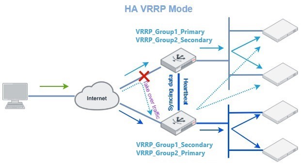
HA-VRRP mode allocates resources into distinct groups, allowing the creation of multiple VRRP groups and the assignment of public IP resources to these groups. This configuration enables an alternative Active-Active mode known as Active-Active-VRRP, commonly referred to as "HA-VRRP." In this mode, each HA node has its own interface IP, while the floating IP is defined on an interface within one of the VRRP groups.
In a typical configuration, connected devices or servers are configured to use the floating IP address associated with the VRRP group as their default gateway. This floating IP is only active on the currently designated active VRRP group. During a failover event, the floating IP transitions to the newly active VRRP group, ensuring that the floating IP remains consistently available.
Refer to Figure 1 above for an example of HA-VRRP mode. In this scenario, two VRRP groups are established: VRRP_Group1 and VRRP_Group2. FortiADC1 is configured as the active node for VRRP_Group1 and the passive node for VRRP_Group2. Conversely, FortiADC2 serves as the passive node for VRRP_Group1 and the active node for VRRP_Group2. The real servers are allocated to these two groups, with servers in VRRP_Group1 pointing their default gateway to the floating IP of VRRP_Group1, and servers in VRRP_Group2 pointing their default gateway to the floating IP of VRRP_Group2.
Under normal operational conditions, FortiADC1 manages the traffic for VRRP_Group1, while FortiADC2 handles traffic for VRRP_Group2. If a failure is detected in any monitored link or device, the HA peer will take over the traffic handling responsibilities to ensure uninterrupted service.
FortiADC units can be deployed as either primary or backup Virtual Router Redundancy Protocol (VRRP) routers and seamlessly integrate into existing VRRP configurations. In a VRRP setup, if a FortiADC unit designated as the primary fails, a backup unit automatically assumes its role, ensuring uninterrupted network traffic processing. Traffic directed to the failed primary unit is transparently redirected to the backup unit. Once the failed FortiADC unit is restored, it reverts to its primary role, resuming traffic processing for the network.
Figure 2: An Active-Active-VRRP cluster configuration using two FortiADC units
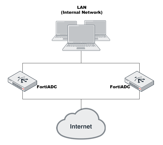
In an Active-Active-VRRP cluster, one node is designated as the primary node for a traffic group, while the remaining nodes serve as member nodes of the group. Traffic from upstream sources can be distributed across up to eight member nodes (one local and seven peers). The Active-Active-VRRP cluster also supports failover: if the primary node fails, the traffic group’s responsibilities are automatically assumed by one of the backup nodes. This backup node will then send a gratuitous ARP message to adjacent devices, updating them to redirect traffic to its own MAC address across all network interfaces within the traffic group.
Active node election process in an Active-Active-VRRP cluster
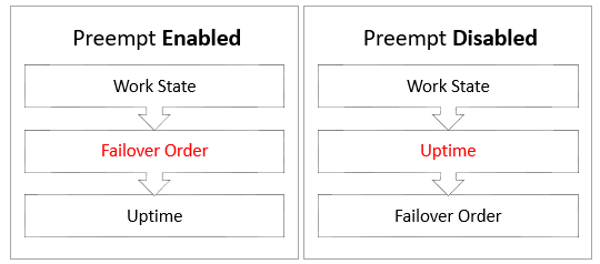
In an Active-Active-VRRP cluster, the Active and Passive nodes are elected by the traffic groups. The system determines the active node by evaluating and prioritizing specific operational conditions and configuration parameters. Depending on whether the Preempt setting has been enabled or disabled, the order each condition is considered differs slightly (illustrated in Figure 3).
Figure 3: Priority Criteria for Active Node Election
|
Criteria |
Description |
|---|---|
| Work State | The "work state" refers to the operational status that is currently influenced solely by the remote IP check. If a device reports a remote IP check failure, it is considered down. In cases where one device shows a failure while another does not, the device without the failure is considered operational. If all devices report a remote IP check failure, the system proceeds to the next criterion. |
|
Failover Order |
Failover order is a configuration option within HA settings. It defines the sequence in which alternative devices should take over based on their Local Node ID. |
| Uptime | The "uptime" refers to the duration the device has been operational. The device with the longest uptime is given precedence. If multiple devices have identical uptime, the system proceeds to the next criterion. |
HA-AA-VRRP configuration steps
The following steps outline the deployment of an Active-Active-VRRP cluster in which each node is configured with two virtual servers: VS1, associated with the VRRP_Group1 traffic group, and VS2, associated with the VRRP_Group2 traffic group. In this setup, traffic directed to VS1 will be managed by FAD1, while traffic to VS2 will be managed by FAD2. In the event of a failure on one of the FortiADC units, the other device will automatically take over its traffic. Port2 is assigned to VRRP_Group1, and Port3 is assigned to VRRP_Group2.
To ensure successful cluster negotiation, all HA devices must use identical heartbeat and data ports, share the same Group ID, and have unique Local Node IDs.
To deploy an Active-Active-VRRP cluster:
-
License all FortiADC appliances in the HA cluster, and register them, including FortiGuard services, with the Fortinet Customer Service & Support website: https://support.fortinet.com/.
- Physically link the FortiADC appliances that make up the HA cluster.
You must link at least one of their ports (for example, port4 to port4) for heartbeat and synchronization traffic between members of the cluster. You can do either of the following:- Connect the two appliances directly with a crossover cable.
- Link the appliances through a switch. If connected through a switch, the heartbeat interfaces must be reachable by Layer 2 multicast.
- Configure the HA settings for each node.
- Log in to the appliance as the admin user.
- Complete the HA settings as described in Configuring HA settings.
The example below shows the configuration for the Primary device FAD1.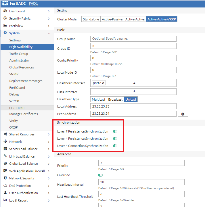
Note: The configuration source is determined by the Config Priority set in the HA setting. When the configuration priority values of the nodes are different, the configuration of the device with the lower configuration priority will prevail. For the secondary node, ensure the Config Priority is set to a number higher than the device you want as the configuration source.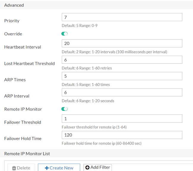

To configure in CLI:
config system ha
  set mode active-active-vrrp
  set hbdev port4 port5
  set group-id 15
  set local-node-id 0
  set group-name grp2
  set config-priority 20
  set override enable
  set l7-persistence-pickup enable
  set l4-persistence-pickup enable
  set l4-session-pickup enable
end
- Configure the required VRRP traffic groups as described in Traffic Group.
Once the devices in the cluster establishes the HA VRRP relationship, then configuration changes that occur on any of the HA nodes can be synchronized to the other nodes. In this example, you can create the traffic groups on one of the nodes, FAD1.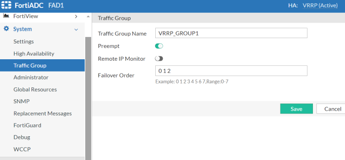
To configure in CLI:
config system traffic-group edit "VRRP_Group1" set failover-order 0 1 set preempt enable next edit "VRRP_Group2" set failover-order 1 0 set preempt enable next end - Assign the interface, virtual server, and other resources to the VRRP traffic group.
By default, all interfaces, virtual servers, and other resources are assigned to the "default" traffic group. It is
recommended to assign these resources to a custom traffic group for better organization and management.- Edit the Interface configuration to associate with the custom traffic group "VRRP_Group1".
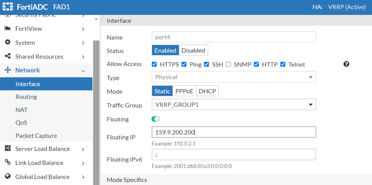
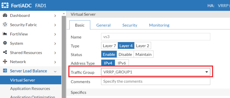
Note that the floating IP only functions within the Primary traffic group. In this example, port2 is part of VRRP_Group1, with FAD1 currently serving as the Primary for VRRP_Group1. As a result, the IP address '159.9.200.200' is currently active on FAD1. If FAD1 fails, FAD2 will assume the role of Primary for VRRP_Group1, and the IP address '159.9.200.200' will then become active on FAD2. - Edit the Virtual Server configurations to associate with their respective customer traffic groups: VS1 to VRRP_Group1 and VS2 to VRRP_Group2.
- Edit the Interface configuration to associate with the custom traffic group "VRRP_Group1".
After saving the HA configuration changes, cluster members will initiate the join or rejoin process within the cluster. Upon saving the configuration on the primary node, it will automatically disseminate the updated configuration to the secondary node through the HA synchronization mechanism.