
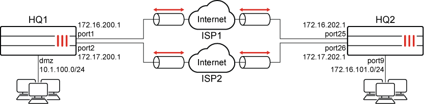
This is a sample configuration of a multiple site-to-site IPsec VPN that uses an IPsec aggregate interface to set up redundancy and traffic load-balancing. The VPN tunnel interfaces must have net-device disabled in order to be members of the IPsec aggregate.
Each FortiGate has two WAN interfaces connected to different ISPs. OSPF runs over the IPsec aggregate in this configuration.
The supported load balancing algorithms are: L3, L4, round-robin (default), weighted round-robin, and redundant. The first four options allow traffic to be load-balanced, while the last option (redundant) uses the first tunnel that is up for all traffic.
Dynamic routing can run on the aggregate interface, and it can be a member interface in SD-WAN (not shown in this configuration).
Configuring the HQ1 FortiGate in the GUI
There are five steps to configure the FortiGate:
To create the IPsec tunnels:
-
Go to VPN > IPsec Wizard and select the Custom template.
-
For Name, enter pri_HQ2 and click Next.
-
Enter the following:
Phase 1
IP Address
172.16.202.1
Interface
port1
Device creation
Disabled
Aggregate member
Enabled
Authentication Method
Pre-shared Key
Pre-shared Key
Enter the secure key
IKE Mode
Aggressive
Peer Options Accept Types
Any peer ID
Phase 2
Auto-negotiate
Enable
-
Configure the other settings as needed.
-
Click OK.
-
Create another tunnel named sec_HQ2 with the following settings:
Phase 1
IP Address
172.17.202.1
Interface
port2
Device creation
Disabled
Aggregate member
Enabled
Authentication Method
Pre-shared Key
Pre-shared Key
Enter the secure key
IKE Mode
Aggressive
Peer Options Accept Types
Any peer ID
Phase 2
Auto-negotiate
Enable
To create the IPsec aggregate:
-
Go to VPN > IPsec Tunnels and click Create New > IPsec Aggregate.
-
For Name, enter agg_HQ2.
-
Select a load balancing algorithm.
-
From the Tunnel dropdown, select the tunnels that you created previously (pri_HQ2 and sec_HQ2). If required, enter weights for each tunnel.
-
Click OK.
To configure the firewall policies:
-
Go to Policy & Objects > Firewall Policy.
-
Create an inbound traffic policy with the following settings:
Name
inbound
Incoming Interface
agg_HQ2
Outgoing Interface
dmz
Source
172.16.101.0
Destination
10.1.100.0
Schedule
always
Action
ACCEPT
Service
ALL
-
Click OK.
-
Create an outbound traffic policy with the following settings:
Name
outbound
Incoming Interface
dmz
Outgoing Interface
agg_HQ2
Source
10.1.100.0
Destination
172.16.101.0
Schedule
always
Action
ACCEPT
Service
ALL
To configure the aggregate VPN interface IPs:
-
Go to Network > Interfaces and edit agg_HQ2.
-
For IP, enter 10.10.10.1.
-
For Remote IP/Netmask, enter 10.10.10.2 255.255.255.255.
-
Click OK.
To configure OSPF:
-
Go to Network > OSPF.
-
For Router ID, enter 1.1.1.1.
-
In the Areas table, click Create New.
-
For Area ID, enter 0.0.0.0.
-
Click OK.
-
-
In the Networks table, click Create New.
-
Set the Area to 0.0.0.0.
-
For IP/Netmask, enter 10.1.100.0/24.
-
Click OK.
-
Click Create New.
-
For IP/Netmask, enter 10.10.10.0/24.
-
Click OK.
-
-
Click Apply.
Configuring the HQ2 FortiGate in the GUI
There are five steps to configure the FortiGate:
To create the IPsec tunnels:
-
Go to VPN > IPsec Wizard and select the Custom template.
-
For Name, enter pri_HQ1 and click Next.
-
Enter the following:
Phase 1
IP Address
172.16.200.1
Interface
port25
Device creation
Disabled
Aggregate member
Enabled
Authentication Method
Pre-shared Key
Pre-shared Key
Enter the secure key
IKE Mode
Aggressive
Peer Options Accept Types
Any peer ID
Phase 2
Auto-negotiate
Enable
-
Configure the other settings as needed.
-
Click OK.
-
Create another tunnel named sec_HQ1 with the following settings:
Phase 1
IP Address
172.17.200.1
Interface
port26
Device creation
Disabled
Aggregate member
Enabled
Authentication Method
Pre-shared Key
Pre-shared Key
Enter the secure key
IKE Mode
Aggressive
Peer Options Accept Types
Any peer ID
Phase 2
Auto-negotiate
Enable
To create the IPsec aggregate:
-
Go to VPN > IPsec Tunnels and click Create New > IPsec Aggregate.
-
For Name, enter agg_HQ1.
-
Select a load balancing algorithm.
-
From the Tunnel dropdown, select the tunnels that you created previously (pri_HQ1 and sec_HQ1). If required, enter weights for each tunnel.
-
Click OK.
To configure the firewall policies:
-
Go to Policy & Objects > Firewall Policy.
-
Create an inbound traffic policy with the following settings:
Name
inbound
Incoming Interface
agg_HQ1
Outgoing Interface
port9
Source
10.1.100.0
Destination
172.16.101.0
Schedule
always
Action
ACCEPT
Service
ALL
-
Click OK.
-
Create an outbound traffic policy with the following settings:
Name
outbound
Incoming Interface
port9
Outgoing Interface
agg_HQ1
Source
172.16.101.0
Destination
10.1.100.0
Schedule
always
Action
ACCEPT
Service
ALL
To configure the aggregate VPN interface IPs:
-
Go to Network > Interfaces and edit agg_HQ1.
-
For IP, enter 10.10.10.2.
-
For Remote IP/Netmask, enter 10.10.10.1 255.255.255.255.
-
Click OK.
To configure OSPF:
-
Go to Network > OSPF.
-
For Router ID, enter 2.2.2.2.
-
In the Areas table, click Create New.
-
For Area ID, enter 0.0.0.0.
-
Click OK.
-
-
In the Networks table, click Create New.
-
Set the Area to 0.0.0.0.
-
For IP/Netmask, enter 172.16.101.0/24.
-
Click OK.
-
Click Create New.
-
For IP/Netmask, enter 10.10.10.0/24.
-
Click OK.
-
-
Click Apply.
Monitoring the traffic in the GUI
To monitor the traffic:
-
Go to Dashboard > Network , hover over the IPsec widget, then click Expand to Full Screen.
-
Expand the aggregate tunnel in the table to view statistics for each aggregate member.
Configuring the HQ1 FortiGate in the CLI
There are six steps to configure the FortiGate:
To configure the interfaces:
-
Configure port1, port2, and dmz as shown in the topology diagram.
To configure two IPsec phase 1 and phase 2 interfaces:
config vpn ipsec phase1-interface
    edit "pri_HQ2"
        set interface "port1"
        set peertype any
        set net-device disable
        set aggregate-member enable
        set proposal aes128-sha256 aes256-sha256 aes128-sha1 aes256-sha1
        set remote-gw 172.16.202.1
        set psksecret sample1
    next
    edit "sec_HQ2"
        set interface "port2"
        set peertype any
        set net-device disable
        set aggregate-member enable
        set proposal aes128-sha256 aes256-sha256 aes128-sha1 aes256-sha1
        set remote-gw 172.17.202.1
        set psksecret sample2
    next
end
config vpn ipsec phase2-interface
    edit "pri_HQ2"
        set phase1name "pri_HQ2"
        set proposal aes128-sha1 aes256-sha1 aes128-sha256 aes256-sha256 aes128gcm aes256gcm chacha20poly1305
        set auto-negotiate enable
    next
    edit "sec_HQ2"
        set phase1name "sec_HQ2"
        set proposal aes128-sha1 aes256-sha1 aes128-sha256 aes256-sha256 aes128gcm aes256gcm chacha20poly1305
        set auto-negotiate enable
    next
end
To configure the IPsec aggregate:
config system ipsec-aggregate
    edit "agg_HQ2"
        set member "pri_HQ2" "sec_HQ2"
    next
end
To configure the firewall policies:
config firewall policy
    edit 1
        set name "inbound"
        set srcintf "agg_HQ2"
        set dstintf "dmz"
        set srcaddr "172.16.101.0"
        set dstaddr "10.1.100.0"
        set action accept
        set schedule "always"
        set service "ALL"
    next
    edit 2
        set name "outbound"
        set srcintf "dmz"
        set dstintf "agg_HQ2"
        set srcaddr "10.1.100.0"
        set dstaddr "172.16.101.0"
        set action accept
        set schedule "always"
        set service "ALL"
    next
end
To configure the aggregate VPN interface IPs:
config system interface
    edit "agg_HQ2"
        set ip 10.10.10.1 255.255.255.255
        set remote-ip 10.10.10.2 255.255.255.255
    next
end
To configure OSPF:
config router ospf
    set router-id 1.1.1.1
    config area
        edit 0.0.0.0
        next
    end
    config network
        edit 1
            set prefix 10.1.100.0 255.255.255.0
        next
        edit 2
            set prefix 10.10.10.0 255.255.255.0
        next
    end
end
Configuring the HQ2 FortiGate in the CLI
There are six steps to configure the FortiGate:
To configure the interfaces:
- Configure port25, port26, and port9 as shown in the topology diagram.
To configure two IPsec phase 1 and phase 2 interfaces:
config vpn ipsec phase1-interface
    edit "pri_HQ1"
        set interface "port25"
        set peertype any
        set net-device disable
        set aggregate-member enable
        set proposal aes128-sha256 aes256-sha256 aes128-sha1 aes256-sha1
        set remote-gw 172.16.200.1
        set psksecret sample1
    next
    edit "sec_HQ1"
        set interface "port26"
        set peertype any
        set net-device disable
        set aggregate-member enable
        set proposal aes128-sha256 aes256-sha256 aes128-sha1 aes256-sha1
        set remote-gw 172.17.200.1
        set psksecret sample2
    next
end
config vpn ipsec phase2-interface
    edit "pri_HQ1"
        set phase1name "pri_HQ1"
        set proposal aes128-sha1 aes256-sha1 aes128-sha256 aes256-sha256 aes128gcm aes256gcm chacha20poly1305
        set auto-negotiate enable
    next
    edit "sec_HQ1"
        set phase1name "sec_HQ1"
        set proposal aes128-sha1 aes256-sha1 aes128-sha256 aes256-sha256 aes128gcm aes256gcm chacha20poly1305
        set auto-negotiate enable
    next
end
To configure the IPsec aggregate:
config system ipsec-aggregate
    edit "agg_HQ1"
        set member "pri_HQ1" "sec_HQ1"
    next
end
To configure the firewall policies:
config firewall policy
    edit 1
        set name "inbound"
        set srcintf "agg_HQ1"
        set dstintf "port9"
        set srcaddr "10.1.100.0"
        set dstaddr "172.16.101.0"
        set action accept
        set schedule "always"
        set service "ALL"
    next
    edit 2
        set name "outbound"
        set srcintf "port9"
        set dstintf "agg_HQ1"
        set srcaddr "172.16.101.0"
        set dstaddr "10.1.100.0"
        set action accept
        set schedule "always"
        set service "ALL"
    next
end
To configure the aggregate VPN interface IPs:
config system interface
    edit "agg_HQ1"
        set ip 10.10.10.2 255.255.255.255
        set remote-ip 10.10.10.1 255.255.255.255
    next
end
To configure OSPF:
config router ospf
    set router-id 2.2.2.2
    config area
        edit 0.0.0.0
        next
    end
    config network
        edit 1
            set prefix 172.16.101.0 255.255.255.0
        next
        edit 2
            set prefix 10.10.10.0 255.255.255.0
        next
    end
end
Monitoring the traffic in the CLI
To view debugging information:
-
Verify the status of the phase 1 IKE SAs:
# diagnose vpn ike gateway list vd: root/0 name: pri_HQ2 version: 1 interface: port1 11 addr: 172.16.200.1:500 -> 172.16.202.1:500 tun_id: 172.16.202.1 created: 1520s ago IKE SA: created 1/2 established 1/1 time 10/10/10 ms IPsec SA: created 2/2 established 1/1 time 0/0/0 ms id/spi: 173 dcdede154681579b/e32f4c48c4349fc0 direction: responder status: established 1498-1498s ago = 10ms proposal: aes128-sha256 key: d7230a68d7b83def-588b94495cfa9d38 lifetime/rekey: 86400/84631 DPD sent/recv: 0000000d/00000006 vd: root/0 name: sec_HQ2 version: 1 interface: port2 12 addr: 172.17.200.1:500 -> 172.17.202.1:500 created: 1520s ago IKE SA: created 1/2 established 1/1 time 10/10/10 ms IPsec SA: created 2/2 established 1/1 time 0/0/0 ms id/spi: 174 a567bd7bf02a04b5/4251b6254660aee2 direction: responder status: established 1498-1498s ago = 10ms proposal: aes128-sha256 key: 9f44f500c28d8de6-febaae9d1e6a164c lifetime/rekey: 86400/84631 DPD sent/recv: 00000008/0000000c -
Verify the phase 2 IPsec tunnel SAs:
# diagnose vpn tunnel list list all ipsec tunnel in vd 0 name=sec_HQ2 ver=1 serial=2 172.17.200.1:0->172.17.202.1:0 tun_id=172.17.202.1 bound_if=5 lgwy=static/1 tun=intf/0 mode=auto/1 encap=none/512 options[0200]=frag-rfc run_state=1 accept_traffic=1 proxyid_num=1 child_num=0 refcnt=7 ilast=5 olast=5 ad=/0 stat: rxp=39 txp=40 rxb=5448 txb=2732 dpd: mode=on-demand on=1 idle=20000ms retry=3 count=0 seqno=15 natt: mode=none draft=0 interval=0 remote_port=0 proxyid=sec_HQ2 proto=0 sa=1 ref=2 serial=2 auto-negotiate src: 0:0.0.0.0/0.0.0.0:0 dst: 0:0.0.0.0/0.0.0.0:0 SA: ref=3 options=18227 type=00 soft=0 mtu=1438 expire=41230/0B replaywin=2048 seqno=29 esn=0 replaywin_lastseq=00000028 itn=0 life: type=01 bytes=0/0 timeout=42899/43200 dec: spi=1071b4f9 esp=aes key=16 1f4dbb78bea8e97650b52d8170b5ece7 ah=sha1 key=20 cd9bf2de0f49296cf489dd915d7baf6d78bc8f12 enc: spi=ec89b7ee esp=aes key=16 0546efecd0d1b9ba5944f635896e4404 ah=sha1 key=20 34599bc7dc25e1ce63ac9615bd50928ce0667dc8 dec:pkts/bytes=39/2796, enc:pkts/bytes=40/5456 name=pri_HQ2 ver=1 serial=1 172.16.200.1:0->172.16.202.1:0 tun_id=172.16.202.1 bound_if=11 lgwy=static/1 tun=intf/0 mode=auto/1 encap=none/512 options[0200]=frag-rfc run_state=1 accept_traffic=1 proxyid_num=1 child_num=0 refcnt=5 ilast=15 olast=15 ad=/0 stat: rxp=38 txp=39 rxb=5152 txb=2768 dpd: mode=on-demand on=1 idle=20000ms retry=3 count=0 seqno=20 natt: mode=none draft=0 interval=0 remote_port=0 proxyid=pri_HQ2 proto=0 sa=1 ref=2 serial=2 auto-negotiate src: 0:0.0.0.0/0.0.0.0:0 dst: 0:0.0.0.0/0.0.0.0:0 SA: ref=3 options=18227 type=00 soft=0 mtu=1438 expire=41231/0B replaywin=2048 seqno=28 esn=0 replaywin_lastseq=00000027 itn=0 life: type=01 bytes=0/0 timeout=42900/43200 dec: spi=1071b4f8 esp=aes key=16 142cce377b3432ba41e64128ade6848c ah=sha1 key=20 20e64947e2397123f561584321adc0e7aa0c342d enc: spi=ec89b7ed esp=aes key=16 2ec13622fd60dacce3d28ebe5fe7ab14 ah=sha1 key=20 c1787497508a87f40c73c0db0e835c70b3c3f42d dec:pkts/bytes=38/2568, enc:pkts/bytes=39/5432 -
Debug the IPsec aggregation list:
# diagnose sys ipsec-aggregate list agg_HQ2 algo=RR member=2 run_tally=2 members: pri_HQ2 sec_HQ2 -
Verify the OSPF neighbor information:
# get router info ospf neighbor
OSPF process 0, VRF 0:
Neighbor ID Pri State Dead Time Address Interface
2.2.2.2 1. Full/ - 00:00:34 10.10.10.2 agg1_HQ2
-
Verify the OSPF routing table:
# get router info routing-table ospf
Routing table for VRF=0
O 172.16.101.0/24 [110/20] via 10.10.10.2, agg1_HQ2 , 00:18:43