
LEDs
|
|
Check your device's QuickStart guide for specific LED information: FortiGate QuickStart Guides. |
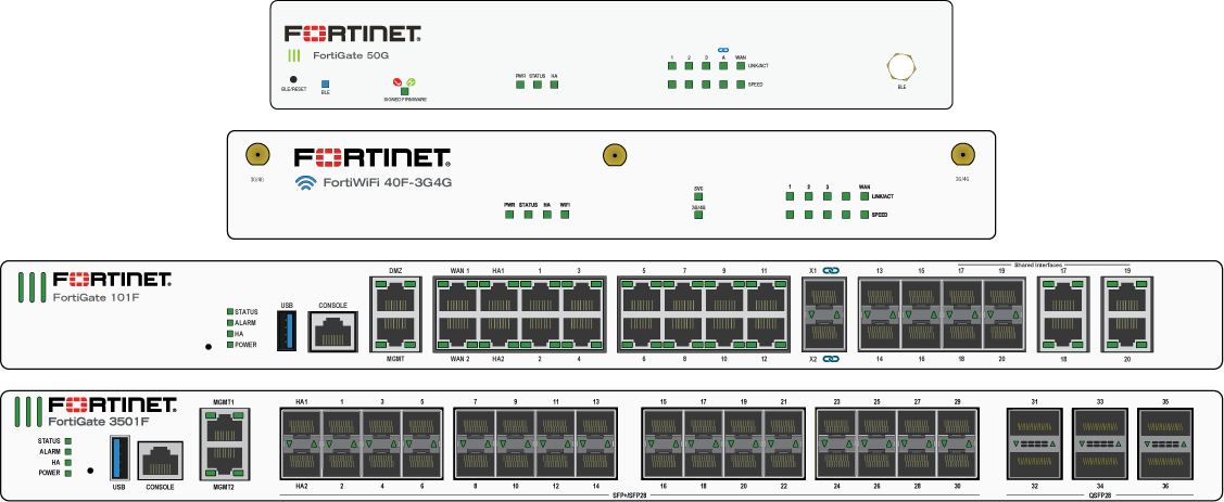
The following faceplates show examples of where the LEDs are typically found on FortiGate models:
The following tables list the possible LED states and their meanings. Not all devices include every LED or support every state.
|
LED |
State |
Description |
|---|---|---|
|
Logo |
Green or Blue |
The unit is on |
|
Off |
The unit is off |
|
|
Power (PWR) |
Green |
The unit is on and/or both power supplies are functioning |
|
Amber or Red |
Only one power supply is functional |
|
|
Flashing Amber or Red |
Power failure |
|
|
Off |
The unit is off |
|
|
Status (STA) |
Green |
Normal |
|
Flashing Green |
Booting up |
|
|
Amber |
Major or minor alarm |
|
|
Red |
Major alarm |
|
|
Flashing Amber or Red |
BLE is on |
|
|
Off |
The unit is off |
|
|
Bypass (BYP) |
Amber |
Bypass Port Pair is active |
|
Off |
Bypass Port Pair is off |
|
|
Alarm |
Red |
|
|
Amber |
||
|
Off |
No alarms |
|
|
HA |
Green |
Operating in an HA cluster |
|
Amber or Red |
HA failover |
|
|
Off |
HA disabled |
|
|
Max PoE |
Green, Amber, or Red |
Maximum PoE power allocated |
|
Off |
PoE power available or normal |
|
|
PoE |
Green |
Power delivered |
|
Flashing Green |
Error or PoE device requesting power |
|
|
Off |
No PoE device connected or no power delivered |
|
|
SVC |
Green |
SVC is on |
|
Flashing Green |
SVC activity |
|
|
Off |
SVC is off |
|
|
3G4G, 3G / 4G |
Green |
3G / 4G service is on |
|
Flashing Green |
3G / 4G activity |
|
|
Off |
3G / 4G service is off |
|
|
WiFi |
Green |
WiFi connected |
|
Flashing Green |
WiFi activity |
|
|
Off |
WiFi is off |
|
|
DSL LINK/ACT |
Green |
DSL connected |
|
Flashing Green |
DSL activity |
|
|
Off |
DSL not connected |
|
|
xDSL |
Green |
VDSL connected |
|
Amber |
ADSL connected |
|
|
Off |
DSL not connected |
|
|
BLE |
Blue |
BLE on |
|
Flashing Blue |
BLE in discovery |
|
|
Off |
BLE off |
|
|
Signed Firmware1 |
Green |
High: Unsigned firmware blocked (default) |
|
Red |
Low: Unsigned firmware allowed with a warning |
|
|
Power supplies and fans |
See your device's QuickStart guide for power supply and fan LED information: FortiGate QuickStart Guides. |
|
1 See BIOS-level signature and file integrity checking for more information.
Port LEDs
|
LED |
State |
Description |
|---|---|---|
|
Ethernet and SFP |
Solid color |
Connected |
|
Flashing color |
Transmitting and receiving data |
|
|
Off |
No link established |
|
|
Speed |
Green |
Connected at maximum speed |
|
Amber |
Connected at a midrange speed |
|
|
Off |
Not connected or connected at minimum speed |
|
|
PoE |
Green |
PoE power on or PoE device receiving power |
|
Amber |
Providing power |
|
|
Red |
Connected but not powered |
|
|
Off |
PoE power off or no device receiving power |
Alarm levels
Minor alarm
Also called an IPMI non-critical (NC) alarm, it indicates a temperature or power level outside of the normal operating range that is not considered a problem. For a minor temperature alarm, the system could respond by increasing the fan speed. A non-critical threshold can be an upper non-critical (UNC) threshold (for example, a high temperature or a high power level) or a lower non-critical (LNC) threshold (for example, a low power level).
Major alarm
Also called an IPMI critical or critical recoverable (CR) alarm, it indicates that the system is unable to correct the cause of the alarm, and that intervention is required. For example, the cooling system cannot provide enough cooling to reduce the temperature. It can also mean that the conditions are approaching the outside limit of the allowed operating range. A critical threshold can also be an upper critical (UC) threshold (such as a high temperature or high power level) or a lower critical (LC) threshold (such as a low power level).
Critical alarm
Also called an IPMI non-recoverable (NR) alarm, it indicates that the system has detected a temperature or power level that is outside of the allowed operating range and physical damage is possible.