


SSL VPN to IPsec VPN
This is a sample configuration of site-to-site IPsec VPN that allows access to the remote endpoint via SSL VPN.
This example uses a pre-existing user group, a tunnel mode SSL VPN with split tunneling, and a route-based IPsec VPN between two FortiGates. All sessions must start from the SSL VPN interface.
If you want sessions to start from the FGT_2 subnet, you need more policies. Also, if the remote subnet is beyond FGT_2 (if there are multiple hops), you need to include the SSL VPN subnet in those routers as well.
Sample topology

Sample configuration
To configure the site-to-site IPsec VPN on FGT_1:
-
Go to VPN > IPsec Wizard.
-
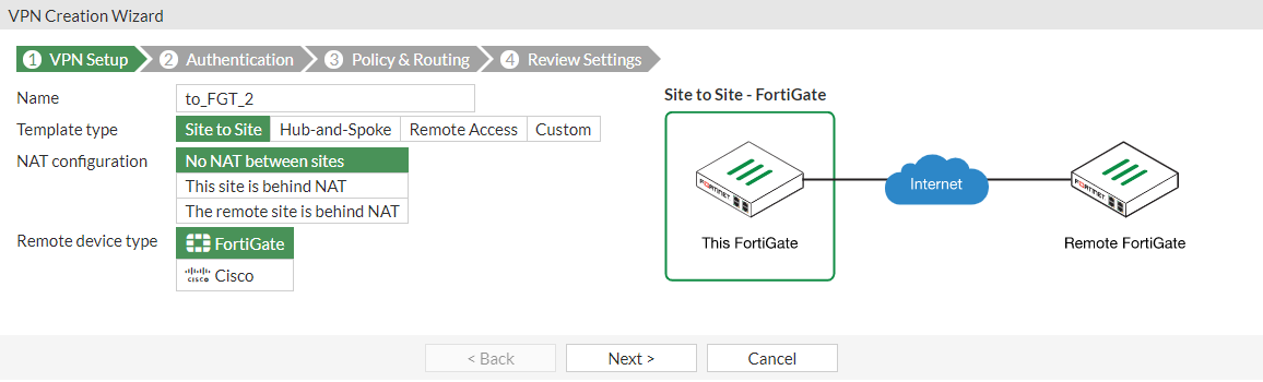
In the VPN Setup pane:
-
Specify the VPN connection Name as to_FGT_2.
-
Select Site to Site.
-
Click Next.
-
-
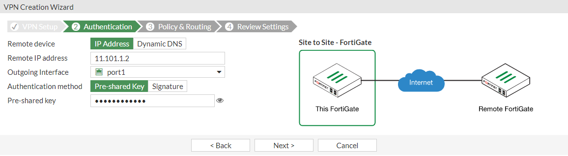
In the Authentication pane:
-
Enter the IP Address to the Internet-facing interface.
-
For Authentication Method, click Pre-shared Key and enter the Pre-shared Key.
-
Click Next.
-
-
In the Policy & Routing pane:
-
Set the Local Interface to the internal interface.
-
Set the Local Subnets to include the internal and SSL VPN subnets for FGT_1.
-
Set Remote Subnets to include the internal subnet for FGT_2.

-
Click Next.
-
-
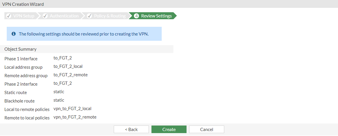
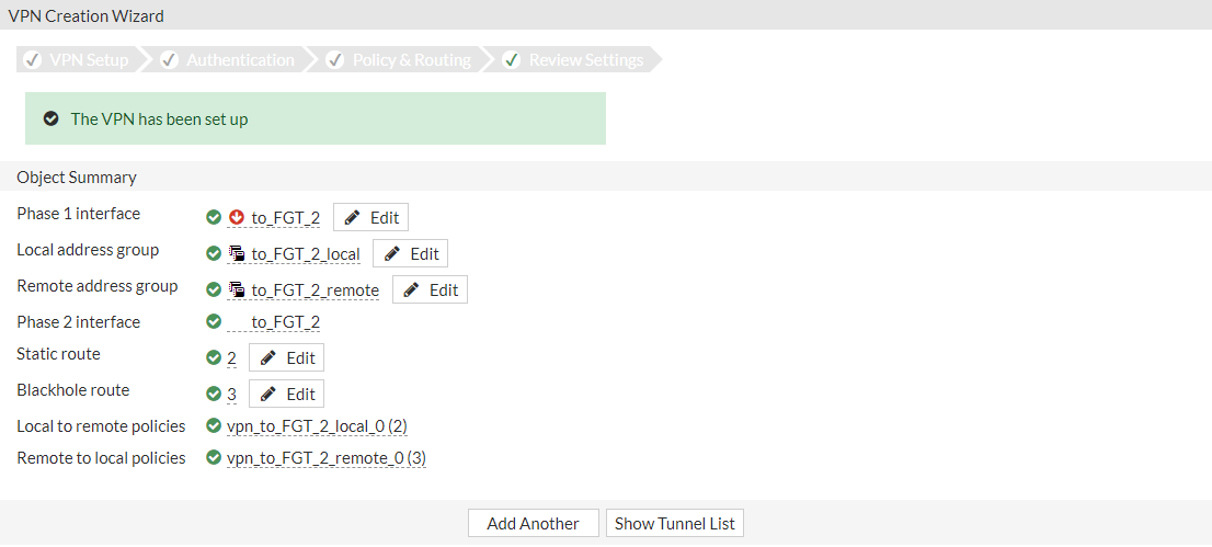
Review the VPN settings and click Create.
A confirmation screen shows a summary of the configuration including the firewall address groups for both the local and remote subnets, static routes, and security policies.
To configure SSL VPN settings:
-
Go to VPN > SSL-VPN Settings.
-
Set Listen on Interface(s) to wan1.
-
To avoid port conflicts, set Listen on Port to 10443.
-
Set Restrict Access to Allow access from any host.
-
In the Tunnel Mode Client Settings section, select Specify custom IP ranges and include the SSL VPN subnet range created by the IPsec Wizard.
-
In the Authentication/Portal Mapping section, add the VPN user group to the tunnel-access Portal. Set All Other Users/Groups to the web-access Portal.


It is HIGHLY recommended that you acquire a signed certificate for your installation. Please review the SSL VPN best practices and learn how to Procuring and importing a signed SSL certificate.
-
Click Apply.
To configure SSL VPN portal:
-
Go to VPN > SSL-VPN Portals.
-
Select tunnel-access and click Edit.
-
Turn on Enable Split Tunneling so that only traffic intended for the local or remote networks flow through FGT_1 and follows corporate security profiles.
-
For Routing Address, add the local and remote IPsec VPN subnets created by the IPsec Wizard.
-
For Source IP Pools, add the SSL VPN subnet range created by the IPsec Wizard.

-
Click OK.
To add policies to FGT_1:
- Go to Policy & Objects > Firewall Policy.
- Click Create New to create a policy that allows SSL VPN users access to the IPsec VPN tunnel.
- For Incoming Interface, select ssl.root.
- For Outgoing Interface, select the IPsec tunnel interface to_FGT_2.
- Set the Source to all and the VPN user group.
- Set Destination to the remote IPsec VPN subnet.
- Specify the Schedule.
- Set the Service to ALL.
- In the Firewall/Network Options section, disable NAT.

- Click OK.
To configure the site-to-site IPsec VPN on FGT_2:
- Go to VPN > IPsec Wizard.
- In the VPN Setup pane:
- Specify the VPN connection Name as to FGT_1.
- Select Site to Site.
- Click Next.
- In the Authentication pane:
- Enter the IP Address to the Internet-facing interface.
- For Authentication Method, click Pre-shared Key and enter the Pre-shared Key of the FGT_1.
- Click Next.
- In the Policy & Routing pane:
- Set the Local Interface to the internal interface.
- Set the Local Subnets to include the internal and SSL VPN subnets for FGT_2.
- Set Remote Subnets to include the internal subnet for FGT_1.
- Click Create.
A confirmation screen shows a summary of the configuration including the firewall address groups for both the local and remote subnets, static routes, and security policies.
To check the results:
-
Go to Dashboard > Network and click the IPsec widget to expand to full screen view.
-
Select the tunnel and click Bring Up.

-
Verify that the Status changes to Up.
-
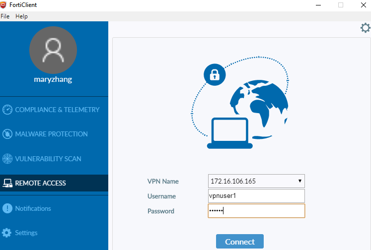
Configure the SSL VPN connection on the user's FortiClient and connect to the tunnel.
-
On the user's computer, send a ping though the tunnel to the remote endpoint to confirm access:
C:\>ping 172.16.200.55 Pinging 172.16.200.55 with 32 bytes of data: Replay from 172.16.200.55: bytes=32 times=2ms TTL=62 Replay from 172.16.200.55: bytes=32 times=1ms TTL=62 Replay from 172.16.200.55: bytes=32 times=1ms TTL=62 Replay from 172.16.200.55: bytes=32 times=1ms TTL=62 Ping statistics for 172.16.200.55: Packets: Sent = 4, Received = 4, Lost = 0 (0% loss), Approximate round trip time in milli-seconds: Minimum = 1ms, Maximum = 2ms, Average = 1ms -
In FortiOS, go to the following pages for further verification:
-
Go to Dashboard > Network and click the Routing widget to verify the IPsec and SSL VPNs are added.
-
Go to VPN > SSL-VPN Clients to verify the connected users.
-
Go to VPN > VPN Location Map to view the connection activity.
-
Go to Log & Report > Events > VPN Events to view tunnel statistics.
-
Go to Dashboard > FortiView Policies to view the policy usage.
-
Troubleshooting
To troubleshoot on FGT_1, use the following CLI commands:
diagnose debug reset
diagnose debug flow show function-name enable
diagnose debug flow show iprope enable
diagnose debug flow filter addr 172.16.200.55
diagnose debug flow filter proto 1
diagnose debug flow trace start 2
diagnose debug enable
To troubleshoot using ping:
- Send a ping through the SSL VPN tunnel to 172.16.200.55 and analyze the output of the debug.
- Disable the debug output with:
diagnose debug disable.
If traffic is entering the correct VPN tunnel on FGT_1, then run the same commands on FGT_2 to check whether the traffic is reaching the correct tunnel. If it is reaching the correct tunnel, confirm that the SSL VPN tunnel range is configured in the remote side quick mode selectors.
To troubleshoot using a sniffer command:
diagnose sniff packet any "host 172.16.200.44 and icmp" 4
To troubleshoot IPsec VPN issues, use the following commands on either FortiGate:
diagnose debug reset
diagnose vpn ike gateway clear
diagnose debug application ike -1
diagnose debug enable