


Simple IS-IS example
This is an example of a typical medium-sized network configuration using IS-IS routing.
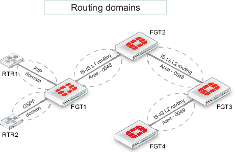
Imagine a company with four FortiGate devices connected to one another. A FortiGate at one end of the network connects to two routers, each with its own local subnet. One of these routers uses OSPF and the other router uses RIP.
Your task is to configure the four FortiGate devices to route traffic and process network updates using IS-IS, so that the farthest FortiGate (see FGT4 in Network layout and assumptions) receives route updates for the two routers at the opposite end of the network. Furthermore, FGT4 has been given a loopback subnet that must be identified by the router running RIP.
Since the internal networks use OSPF and RIP, those protocols need to be redistributed throughout the IS-IS network. To keep the example simple, there will be no authentication of router traffic.
With IS-IS properly configured in this example, if a router fails or temporarily goes offline, the route change will propagate throughout the system.
Network layout and assumptions

- It's assumed that each FortiGate is operating in NAT mode, running FortiOS 4.0MR2+.
- All interfaces have been previously assigned and no static routes are required.
- The Authority and Format Identifier (AFI) used is 49 : Locally administered (private).
- The Area identifiers are 0048 and 0049.
Expectations
- FGT4 must get the IS-IS route updates for RTR1 and RTR2 local subnets (10.1.1.0, 10.2.2.0, 10.3.3.0, 10.4.4.0).
- RTR1 must receive (via RIP2) the loopback subnet of FGT4 (10.60.60.1/32).
CLI configuration
The following CLI configuration occurs on each FortiGate (as identified), including only the relevant parts.
FGT1
config router isis
config isis-interface
edit "port3"
set circuit-type level-1
set network-type broadcast
set status enable
next
end
config isis-net
edit 1
set net 49.0048.1921.6818.2136.00
next
end
config redistribute "connected"
end
config redistribute "rip"
set status enable
set level level-1
end
config redistribute "ospf"
set status enable
set level level-1
end
end
config router rip
config interface
edit "port2"
set receive-version 2
set send-version 2
next
end
config network
edit 1
set prefix 10.10.10.0 255.255.255.0
next
end
config redistribute "isis"
set status enable
end
end
FGT2
config router isis
config isis-interface
edit "port3"
set circuit-type level-1
set network-type broadcast
set status enable
next
edit "port2"
set network-type broadcast
set status enable
next
end
config isis-net
edit 1
set net 49.0048.1221.6818.2110.00
next
end
set redistribute-l1 enable
set redistribute-l2 enable
end
FGT3
config router isis
set is-type level-2-only
config isis-interface
edit "wan1"
set network-type broadcast
set status enable
next
edit "dmz1"
set network-type broadcast
set status enable
next
end
config isis-net
edit 1
set net 49.0048.1921.6818.2108.00
next
edit 2
set net 49.0049.1921.6818.2108.00
next
end
end
FGT4
config router isis
set is-type level-2-only
config isis-interface
edit "wan1"
set network-type broadcast
set status enable
next
end
config isis-net
edit 1
set net 49.0049.1721.0160.1004.00
next
end
config redistribute "connected"
set status enable
end
end
Verification
Once the network has been configured, you need to test that it works as expected. Use the following CLI commands on the devices indicated.
Verifying if RTR1 receives loopback subnet of FGT4
(RTR1) # get router info routing-table all
Result:
C 10.1.1.0/24 is directly connected, vlan1
C 10.2.2.0/24 is directly connected, vlan2
C 10.10.10.0/24 is directly connected, dmz1
R 10.40.40.0/24 [120/2] via 10.10.10.1, dmz1, 00:04:07
R 10.50.50.0/24 [120/2] via 10.10.10.1, dmz1, 00:04:07
R 10.60.60.1/32 [120/2] via 10.10.10.1, dmz1, 00:04:07
(*) If required, filtering out 10.50.50.0 and 10.40.40.0 from the routing table could be done with a route-map.
Verification on FGT2, which is the border between L1 and L2 routing levels, looking at IS-IS information
FGT2 # get router info isis interface
Result:
port2 is up, line protocol is up
Routing Protocol: IS-IS ((null))
Network Type: Broadcast
Circuit Type: level-1-2
Local circuit ID: 0x01
Extended Local circuit ID: 0x00000003
Local SNPA: 0009.0f85.ad8c
IP interface address:
10.40.40.2/24
IPv4 interface address:
Level-1 Metric: 10/10, Priority: 64, Circuit ID: 1221.6818.2110.01
Number of active level-1 adjacencies: 0
Level-2 Metric: 10/10, Priority: 64, Circuit ID: 1221.6818.2110.01
Number of active level-2 adjacencies: 1
Next IS-IS LAN Level-1 Hello in 6 seconds
Next IS-IS LAN Level-2 Hello in 1 seconds
port3 is up, line protocol is up
Routing Protocol: IS-IS ((null))
Network Type: Broadcast
Circuit Type: level-1
Local circuit ID: 0x02
Extended Local circuit ID: 0x00000004
Local SNPA: 0009.0f85.ad8d
IP interface address:
10.30.30.2/24
IPv4 interface address:
Level-1 Metric: 10/10, Priority: 64, Circuit ID: 1221.6818.2110.02
Number of active level-1 adjacencies: 1
Next IS-IS LAN Level-1 Hello in 2 seconds

FGT2 # get router info isis neighbor
Result:
|
System Id |
Interface |
SNPA |
State |
Holdtime |
Type |
Protocol |
|
1921.6818.2108 |
port2 |
0009.0f04.0794 |
Up |
22 |
L2 |
IS-IS |
|
1921.6818.2136 |
port3 |
0009.0f85.acf7 |
Up |
29 |
L1 |
IS-IS |
Verification on FGT3, which is border between 2 areas, looking at IS-IS information
IS-IS router CLI commands available:
FGT3 # get router info isis ?
Result:
|
|
|
|
|
|
|
|
|
|
|
|
|
|
|
|
|
|
Example of interface status and neighbors:
FGT3 # get router info isis interface
Result:
wan1 is up, line protocol is up
Routing Protocol: IS-IS ((null))
Network Type: Broadcast
Circuit Type: level-1-2
Local circuit ID: 0x01
Extended Local circuit ID: 0x00000003
Local SNPA: 0009.0f04.0794
IP interface address:
10.40.40.1/24
IPv4 interface address:
Level-2 Metric: 10/10, Priority: 64, Circuit ID: 1221.6818.2110.01
Number of active level-2 adjacencies: 1
Next IS-IS LAN Level-2 Hello in 3 seconds

dmz1 is up, line protocol is up
Routing Protocol: IS-IS ((null))
Network Type: Broadcast
Circuit Type: level-1-2
Local circuit ID: 0x02
Extended Local circuit ID: 0x00000005
Local SNPA: 0009.0f04.0792
IP interface address:
10.50.50.1/24
IPv4 interface address:
Level-2 Metric: 10/10, Priority: 64, Circuit ID: 1721.0160.1004.01
Number of active level-2 adjacencies: 1
Next IS-IS LAN Level-2 Hello in 7 seconds

FGT3 # get router info isis neighbor
Result:
|
System Id |
Interface |
SNPA |
State |
Holdtime |
Type |
Protocol |
|
1221.6818.2110 |
wan1 |
0009.0f85.ad8c |
Up |
8 |
L2 |
IS-IS |
|
1721.0160.1004 |
dmz1 |
0009.0f52.7704 |
Up |
8 |
L2 |
IS-IS |
Verification on FGT4 that the remote subnets from RTR1 and RTR2 are in the routing table and learned with IS-IS
FGT4 # get router info routing-table all
Result:
Codes: K - kernel, C - connected, S - static, R - RIP, B - BGP
O - OSPF, IA - OSPF inter area
N1 - OSPF NSSA external type 1, N2 - OSPF NSSA external type 2
E1 - OSPF external type 1, E2 - OSPF external type 2
i - IS-IS, L1 - IS-IS level-1, L2 - IS-IS level-2, ia - IS-IS inter area
* - candidate default
i L2 10.1.1.0/24 [115/30] via 10.50.50.1, wan1, 00:12:46
i L2 10.2.2.0/24 [115/30] via 10.50.50.1, wan1, 00:12:46
i L2 10.3.3.0/24 [115/30] via 10.50.50.1, wan1, 00:12:46
i L2 10.4.4.0/24 [115/30] via 10.50.50.1, wan1, 00:12:46
i L2 10.10.10.0/24 [115/30] via 10.50.50.1, wan1, 00:12:46
i L2 10.11.11.0/24 [115/30] via 10.50.50.1, wan1, 00:12:46
i L2 10.20.20.0/24 [115/30] via 10.50.50.1, wan1, 00:12:46
i L2 10.30.30.0/24 [115/30] via 10.50.50.1, wan1, 00:13:55
i L2 10.40.40.0/24 [115/20] via 10.50.50.1, wan1, 00:15:30
C 10.50.50.0/24 is directly connected, wan1
C 10.60.60.1/32 is directly connected, loopback
Troubleshooting
The following diagnose commands are available for further IS-IS troubleshooting and will display all IS-IS activity (sent and received packets):
FGT # diagnose ip router isis level info
FGT # diagnose ip router isis all enable
FGT # diagnose debug enable
...to stop the debug type output:
FGT # diagnose ip router isis level none
Output and interpretation depends on the issue faced. You can provide this information to TAC if you open a support ticket.