


Configuring an unsupported modem
This section provides information about how to configure FortiOS to support unsupported USB modems.
Modem terminology
The FortiOS CLI includes three modem-related configuration commands:
The config system lte-modem command enables LTE modem support and can be used to configure communication with LTE modems that have Ethernet-like back end interfaces. This is most LTE modems.
The config system modem command enables modem support on the GUI and is used to configure the FortiGate to work with a PPP modem.
The config system 3g-modem command allow mode switching for unsupported modems.
It's important to understand what's going on inside a USB modem. There are two parts of the hardware: front-end and back-end. The front-end runs UMTS, HRPD, LTE or similar languages. The back end runs PPP or an Ethernet-like protocol to talk to the host. During the 3G modem era, the mainstream technology used in the back end was PPP protocol. Later 4G and LTE technology came into play and modem companies added LTE capable hardware in the front-en.
Now LTE dominates the wireless network and most modems that you would connect to a FortiGate are LTE modems. Some LTE modems still use the same PPP back end. Some USB communication specs similar to Ethernet that have been developed in recent years, like EEM, ECM, NCM, MBIM are mostly paired with LTE technology in current LTE modems.
About mode switching
For a USB modem to work on a PC, the device driver and modem utilities have to be installed. In most cases, the easiest way to get these drivers and utilities into the PC is to store them on the USB modem device. When a USB modem with mode switch implemented is plugged into a PC USB port, it appears to be a USB storage device first, the device driver and modem utilities can be installed from the storage device. After installation, running the modem utility sends USB messages to the USB device causing it to switch modes from a USB storage device to a USB modem device. This is called mode switching.
Different modems have different mode switch messages. FortiOS can support a USB modem if it can successfully determine which modem has been connected and send the correct mode switch messages to it. If FortiOS doesn't support a USB modem, you can manually configure the mode switching messages for the modem using the config system 3g-modem custom command.
|
|
For mode switching to work you have to enable modem support using one of the following commands: config system modem set status enable end or config system lte-modem set status enable end |
Supported modem protocols
FortiOS can simultaneously manage multiple modems supporting the PPP protocol.
Most LTE modems use an ethernet-link protocol, and a single FortiGate can only manage one LTE modem that uses an Ethernet-like protocol. FortiOS includes the following drivers to support various ethernet-like modem protocols:
- The
CDCEtherandcdc_etherdrivers support many modems that have Ethernet-like functionality. FortiGates with the 2.4 kernel include theCDCEtherdriver and FortiGates with the 3.2 kernel include thecdc-etherdriver. Both drivers support the same functionality. - The
sierra_netdriver supports most Sierra and NetGear modems. - The
cdc_ncmandhuawei_cdc_ncmdrivers support the NCM protocol; which is widely used by Huawei modems. Modems from other vendors might also run thecdc_ncmprotocol. Thehuawei_cdc_ncmdriver is a customized NCM protocol by Huawei that is only supported by FortiGates running the 3.2 kernel. - The
GobiNetdriver is a Qualcomm protocol, used by some modems with Qualcomm chips. - The
qmi_wwandriver is a mature and widely used protocol supported by modems with Qualcomm wireless chips. - The
rndis_hostdriver supports a protocol similar tocdc_ether. - Marvell modems using the WiFi-Ex driver. Marvell modems should work with the default ForiOS configuration after you enable LTE modem functionality. The vendor id is 1286, product id is 4e31.
Viewing information about a USB modem
You can use the following command to list all of the USB devices connected to your FortiGate.
fnsysctl cat /proc/bus/usb/devices
If you have not connected a USB modem, the command output shows information about each of the USB devices. If you connect a USB modem, it will appear in the output. For example, the following output appears from a FortiGate-51E with an attached Sierra Aircard 33OU LET modem. The output shows three USB devices. The third one is the modem.
fnsysctl cat /proc/bus/usb/devices

T:  Bus=03 Lev=00 Prnt=00 Port=00 Cnt=00 Dev#=  1 Spd=5000 MxCh= 1
B:  Alloc=  0/800 us ( 0%), #Int=  0, #Iso=  0
D:  Ver= 3.00 Cls=09(hub  ) Sub=00 Prot=03 MxPS= 9 #Cfgs=  1
P:  Vendor=1d6b ProdID=0003 Rev= 3.02
S:  Manufacturer=Linux 3.2.16 xhci-hcd
S:  Product=xHCI Host Controller
S:  SerialNumber=f10f0000.usb3
C:* #Ifs= 1 Cfg#= 1 Atr=e0 MxPwr=  0mA
I:* If#= 0 Alt= 0 #EPs= 1 Cls=09(hub  ) Sub=00 Prot=00 Driver=hub
E:  Ad=81(I) Atr=03(Int.) MxPS=   4 Ivl=256ms

T:  Bus=02 Lev=00 Prnt=00 Port=00 Cnt=00 Dev#=  1 Spd=480  MxCh= 1
B:  Alloc=  0/800 us ( 0%), #Int=  0, #Iso=  0
D:  Ver= 2.00 Cls=09(hub  ) Sub=00 Prot=01 MxPS=64 #Cfgs=  1
P:  Vendor=1d6b ProdID=0002 Rev= 3.02
S:  Manufacturer=Linux 3.2.16 xhci-hcd
S:  Product=xHCI Host Controller
S:  SerialNumber=f10f0000.usb3
C:* #Ifs= 1 Cfg#= 1 Atr=e0 MxPwr=  0mA
I:* If#= 0 Alt= 0 #EPs= 1 Cls=09(hub  ) Sub=00 Prot=00 Driver=hub
E:  Ad=81(I) Atr=03(Int.) MxPS=   4 Ivl=256ms

T:  Bus=02 Lev=01 Prnt=01 Port=00 Cnt=01 Dev#=  7 Spd=480  MxCh= 0
D:  Ver= 2.00 Cls=00(>ifc ) Sub=00 Prot=00 MxPS=64 #Cfgs=  1
P:  Vendor=1199 ProdID=68a3 Rev= 0.06
S:  Manufacturer=Sierra Wireless, Incorporated
S:  Product=AirCard 330U
S:  SerialNumber=359615040996060
C:* #Ifs= 7 Cfg#= 1 Atr=a0 MxPwr=500mA
I:* If#= 0 Alt= 0 #EPs= 2 Cls=ff(vend.) Sub=ff Prot=ff Driver=usbserial_generic
E:  Ad=81(I) Atr=02(Bulk) MxPS= 512 Ivl=0ms
E:  Ad=01(O) Atr=02(Bulk) MxPS= 512 Ivl=4ms
I:* If#= 1 Alt= 0 #EPs= 2 Cls=ff(vend.) Sub=ff Prot=ff Driver=usbserial_generic
E:  Ad=82(I) Atr=02(Bulk) MxPS= 512 Ivl=0ms
E:  Ad=02(O) Atr=02(Bulk) MxPS= 512 Ivl=4ms
I:* If#= 2 Alt= 0 #EPs= 2 Cls=ff(vend.) Sub=ff Prot=ff Driver=usbserial_generic
E:  Ad=83(I) Atr=02(Bulk) MxPS= 512 Ivl=0ms
E:  Ad=03(O) Atr=02(Bulk) MxPS= 512 Ivl=4ms
I:* If#= 3 Alt= 0 #EPs= 3 Cls=ff(vend.) Sub=ff Prot=ff Driver=usbserial_generic
E:  Ad=84(I) Atr=03(Int.) MxPS=  64 Ivl=2ms
E:  Ad=85(I) Atr=02(Bulk) MxPS= 512 Ivl=0ms
E:  Ad=04(O) Atr=02(Bulk) MxPS= 512 Ivl=4ms
I:* If#= 4 Alt= 0 #EPs= 3 Cls=ff(vend.) Sub=ff Prot=ff Driver=usbserial_generic
E:  Ad=86(I) Atr=03(Int.) MxPS=  64 Ivl=2ms
E:  Ad=87(I) Atr=02(Bulk) MxPS= 512 Ivl=0ms
E:  Ad=05(O) Atr=02(Bulk) MxPS= 512 Ivl=4ms
I:* If#= 9 Alt= 0 #EPs= 2 Cls=08(stor.) Sub=06 Prot=50 Driver=usbserial_generic
E:  Ad=06(O) Atr=02(Bulk) MxPS= 512 Ivl=0ms
E:  Ad=88(I) Atr=02(Bulk) MxPS= 512 Ivl=0ms
I:* If#= 7 Alt= 0 #EPs= 3 Cls=ff(vend.) Sub=ff Prot=ff Driver=sierra_net
E:  Ad=89(I) Atr=03(Int.) MxPS=  64 Ivl=2ms
E:  Ad=8a(I) Atr=02(Bulk) MxPS= 512 Ivl=0ms
E:  Ad=07(O) Atr=02(Bulk) MxPS= 512 Ivl=4ms
The entry for the modem includes information you can use to set up a custom configuration, including the Vendor ID (1199) and the Product ID (68a3) and so on. The command output also shows the driver that FortiOS has assigned to this device (sierra_net). All this indicates that FortiOS has identified the modem and that it is supported as a modem and not as a USB storage device.
More about USB device information
The following table explains some of the USB information displayed by the fnsysctl cat /proc/bus/usb/devices command.
|
Tag |
Meaning |
Notes |
|---|---|---|
| T: | Topology | This line shows the position of the device in the USB tree topology. |
| D: | Device descriptor | Each USB device has a device descriptor. It includes all the lines after this tag. |
| B: | Bandwidth descriptor | - |
| #Cfgs | Number of configurations | Each USB device has one or more configurations, but only one is active. |
| C: | Configuration descriptor | The active configuration has a star symbol, * , to the right. |
| I: | Interface descriptor | The * symbol means the interface descriptor is active. |
| #Ifs | Number of Interfaces | A USB configuration includes one or more USB interface descriptors. |
| Cfg# | Index of configuration descriptor | - |
| Alt | Alternative interface descriptor ID | Each USB interface under a USB configuration may have multiple alternative interface descriptors, but only one is active. |
| #EPs | Number of endpoints | Each USB interface consists of several USB endpoints. |
| Cls, Sub, Prot |
Interface class Interface sub class Interface protocol |
These are important elements in CDC definitions. |
| Driver= | USB interface driver | Each USB interface binds to a specific USB driver if supported by the host, otherwise it means the host doesn't know this device, it shows (None). |
| Ad= | Address of the USB endpoint | Each USB device can have up to 30 endpoints, 0 is reserved as control endpoint, the other endpoints are addressed from 1-15 and direction in or out. |
| (I) and (O) | Direction of the endpoint | In or Out. |
| Int/Bulk/Isoc/Ctrl | Type of Endpoint | Interrupt, Bulk, Isochronous, Control, four types of endpoints. |
Mode switching example
The fnsysctl cat /proc/bus/usb/devices command displays information similar to the following for an unsupported modem (in this case a Dlink DWR-910 modem):

In this output, the vendor ID is 0x2001, the Product ID is 0xa40d, and it appears as a storage device. Mode switching is required to support this device as a USB modem.
|
|
You can find information about and sources for mode switch utilities from the website: http://www.drasberghof.de/usb_modeswitch/. |
You can find out how to mode switch a modem by installing a usb mode switching utility on a PC. For example you could install the usb_modeswitch utility on a Linux.The following screen grab shows how to find the message you'll need to mode switch a modem. Fedora 20 and mode switch v 2.4 were used in this example.

The database of the mode switch messages can be found here:

The two parts of hex strings are the Vendor ID and Product ID of the USB storage devices. For example:

This example shows a Huawei modem, the original Product ID is 1031, after the switch it should become 1035, and the mode switch USB message is the value of "MessageContent", which is a long hex string.
An example Dlink-DWR-910 modem could respond with the following:

The Product ID is 7e38, but the mode switch message must include a StandardEject=1 statement instead of just a string like the previous example. From searching the source code of usb_modeswitch, you can determine that to perform a standard eject, the FortiGate must send the following two messages to the modem:
5553424312345678000000000001061e000000000000000000000000000000
5553424312345679000000000001061b000000020000000000000000000000
To configure the FortiGate to mode switch the example Dlink-DWR-910 modem requires adding the following configuration using the config system system 3g-modem custom command:
config system 3g-modem custom
edit 1
set vendor DLINK
set model DWR-910
set vendor-id 2001
set product-id a40d
set init-string "inquire=1 msg=5553424312345678000000000001061e000000000000000000000000000000"
next
edit 2
set vendor DLINK
set model DWR-910
set vendor-id 2001
set product-id a40d
set init-string "inquire=1 msg=5553424312345679000000000001061b000000020000000000000000000000"
end
If you have multiple entries for a same modem in the configuration, you should have the keyword inquire=1 in the init-string command. If there’s only one entry, it is not needed. The multiple entries will be executed in the order they are listed in the configuration.
Once you have entered this configuration, you can cause the mode switch to occur by enabing modem support using one of the following commands:
config system modem
set status enable
end
or
config system lte-modem
set status enable
end
Then, when the modem is inserted, the mode switch will occur and a new USB device will appear when you enter the fnsysctl cat /proc/bus/usb/devices command.

Now the DWR-910 modem is switched into a device running the rndis_host driver.This device has two configurations, the first is an rndis_host device, and the second configuration is not active, and the interfaces are not identified by FortiOS. An advanced USB developer can identify that it's a cdc_ether device, because the interface 0 of configuration 2 has class=2, subclass=6, and protocol=0, also the interface 1 has class=a, subclass=0, and protocol=0.
More mode switching examples
The following are a few more modem mode-switching examples.
ZTE MF823 example
Installing a ZTE MF823 modem and running the fnsysctl cat /proc/bus/usb/devices command shows the following:
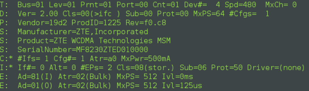
You can use the following configuration to initiate mode switching for the ZTE MF823 modem:
config system 3g-modem custom
edit 1
set vendor ZTE
set model MF823
set vendor-id 19d2
set product-id 1225
set init-string "inquire=1 msg=5553424312345678000000000001061e000000000000000000000000000000"
next
edit 2
set vendor ZTE
set model MF823
set vendor-id 19d2
set product-id 1225
set init-string "inquire=1 msg=5553424312345679000000000001061b000000020000000000000000000000"
end
The output of the fnsysctl cat /proc/bus/usb/devices command now shows the or the ZTE MF823 modem is a cdc_ether device:

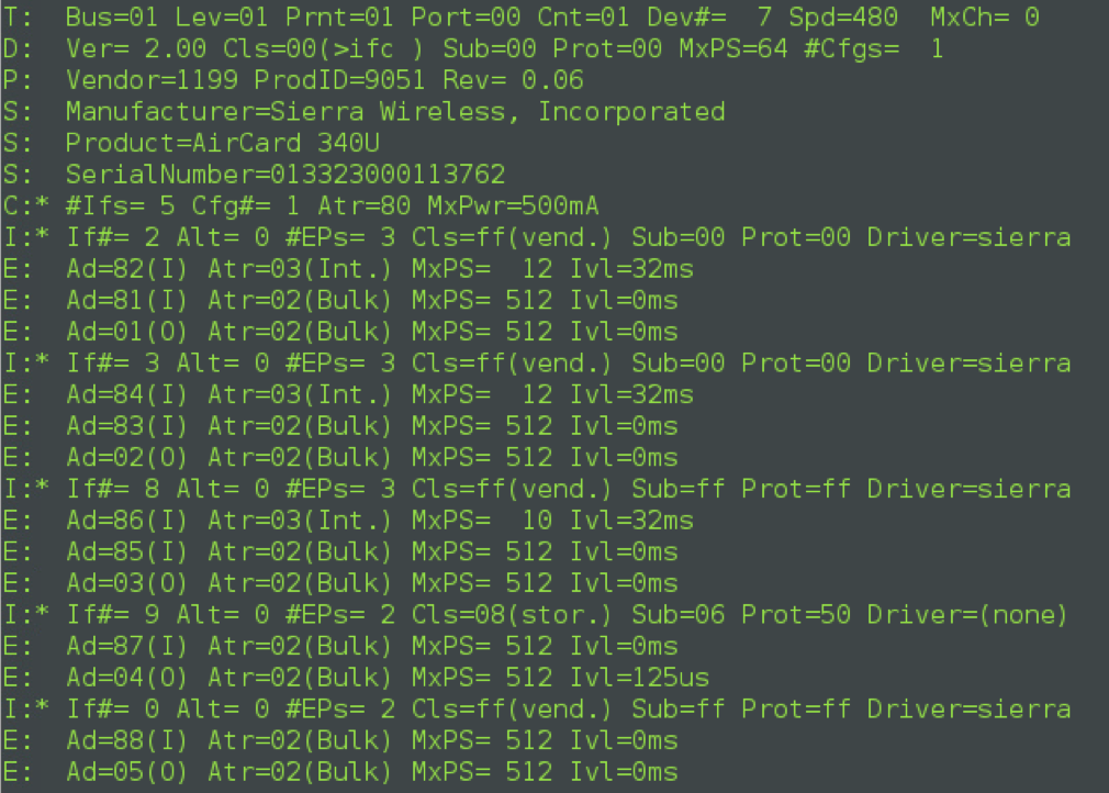
Sierra Wireless 340U example
The fnsysctl cat /proc/bus/usb/devices command output for the Sierra 340U shows that this is a PPP modem because it doesn't have any Ethernet interfaces. So the modem configuration should be set using config system modem and not config system lte-modem.
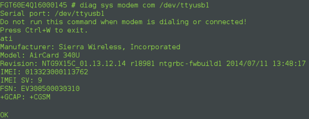
The output of the diagnose sys modem com /dev/ttyusb1 command shows that the modem port is /dev/ttyusb1, and in modem configuration the wireless port to should be 2 because the modem daemon counts from 1, port 1 means ttyusb0.
Sierra Wireless 313U example
The fnsysctl cat /proc/bus/usb/devices command output for the Sierra Wireless 313U identifies the first 5 interfaces as serial interfaces that use the sierra driver. The last interface is a sierra_net interface, and it is an Ethernet-like interface, supported by the FortiOS LTE daemon.

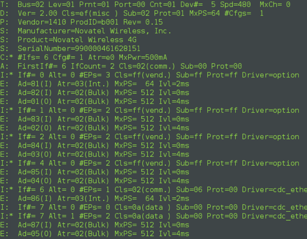
Novatel U551L example
The fnsysctl cat /proc/bus/usb/devices command output shows that the Novatel U551L is a cdc_ether device, the last two interfaces form a cdc_ether union, and it is supported by the FortiOS LTE daemon. The first four interfaces are identified as serial ports which use the option driver.
Identifying the modem port
After successfully mode switching a modem, the next thing to do is to identify the modem port, or identify what the index of the modem port is.
The easiest and most reliable way to find the modem port is to use the command: diagnose sys modem com /dev/ttyusb<X>. where <x> is the modem port number.
In the following example the modem port number is /dev/ttyusb1:

Identifying the LTE modem interface
You can use the fnsysctl ifconfig wwan command to identify the LTE modem interface. Before you can use the command you must delete all config system modem configurations and enable the LTE modem configuration:
config system modem
set status disable
end
config system lte-modem
set status enable
end
With a recognized and mode switched modem inserted and powered up, runing the fnsysctl ifconfig wwan command should show information about the wwan interface created by FortiOS when you connect a recognized modem:
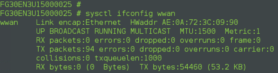
The command output shows that the interface exists, and it seems to be working properly, although it hasn't received an IP address yet because the SIM card is missing.
Troubleshooting and debugging
After inserting a SIM card into the LTE modem and connecting it to the USB port, use get system interface to see if the LTE modem interface (wwan) appears on the interface list and if it has an IP address. In the following example, the wwan interface appears but doesn't have an IP address:

Changing the LTE modem port
Enter the following commands to verify the modem port:

Next, set debug mask to 31, which enables debug levels 0, 1, 2, 4, 8, 16.
Enter diagnose test application lted 1 to check the modem info.
The error message failed to read_modem_device may indicate that the modem port may not be set correctly. It's possible that you might have other USB devices plugged into the USB port, and there's also a USB serial port on the external USB devices, which disrupts the default USB serial port order. This may cause the modem to fail.
You can use the following command to try changing the modem port to port 3. The default is port 0:
config system lte-modem
set modem-port 3
end
Try the above commands again to see if FortiOS is using the new modem port. The command output now shows that the modem port is working but its still not connected:

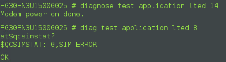
The diagnose test application lted 14 command can show if something else is wrong. The following output shows a SIM ERROR indicating that the SIM card is missing or not installed correctly.
Still not working?
If you have tried all this and its still nor working, contact Fortinet Support.