
FS-AX9000G-SUP supervisor
The FS-AX9000G-SUP is the basic FortiSwitch-AX9000G control module.
FS-AX9000G-SUP front panel
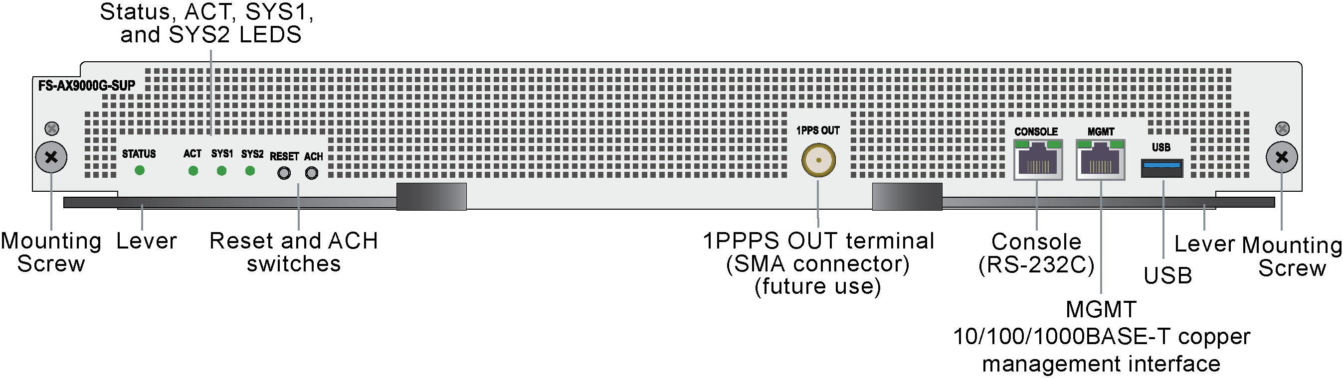
Front panel interfaces
The FS-AX9000G-SUP includes the following interfaces:
-
CONSOLE, RS-232C console port
-
MGMT, 10/100/1000BASE-T management interface
-
USB, USB-A port
Physical description
|
Max power consumption |
614W /565W (Input Power Base/Output Power Base. Output power = input power x 0.92) |
|
Dimensions |
2.0 x 17.2 x 19.8in (50.7 x 436 x 500.5mm) |
|
Weight |
18.5lbs (8.4 kg) |
|
Operating temperature |
32 to 104°F (0 to 40°C) |
|
Storage temperature |
-13 to 149°F (-25 to 65°C) |
|
Relative humidity |
5 to 85% (recommended value 45 to 55%) |
Front panel LEDs
|
LED |
State |
Description |
|---|---|---|
|
STATUS
|
Off |
The FS-AX9000G-SUP is powered off. |
|
Green |
The FS-AX9000G-SUP is powered on and operating normally. |
|
| Flashing Green |
The FS-AX9000G-SUP is starting up or has been stopped by inputting the |
|
|
Red |
Supervisor fault detected. |
|
|
Flashing Red |
Supervisor temperature abnormality. |
|
|
ACT
|
Off |
The FS-AX9000G-SUP is in standby mode or is powered off. In a chassis with two FS-AX9000G-SUPs, this is the standby or backup FS-AX9000G-SUP. |
|
Green |
The FortiSwitch-AX9004G is operating. In a chassis with two FS-AX9000G-SUPs, this is the active FS-AX9000G-SUP. |
|
|
SYS1
|
Off |
The equipment is powered off. |
|
Green |
The equipment is powered on and operating normally. |
|
|
Flashing Red |
Partial equipment failure detected. |
|
|
Red |
Equipment failure detected. |
|
|
SYS2 |
Not supported |
|
|
LINK
|
Off |
Network cable is not connected or link failure or operation is stopped. |
|
Green |
Link established. |
|
|
Orange |
Fault detected. |
|
|
T/R
|
Off |
No traffic. |
|
Green |
Packets are being sent or received. |
Front panel switches
|
Switch |
Description |
|---|---|
|
RESET |
Manual reset switch. Press for 1 second to restart the FS-AX9000G-SUP. Press and hold for 10 seconds to reset the FS-AX9000G-SUP to factory defaults. |
|
ACH |
If the FortiSwitch-AX9004G has two FS-AX9000G-SUPs, you can change which FS-AX9000G-SUP is operating as the active and which is operating as the standby. After the switchover, the new standby FS-AX9000G-SUP restarts. |
|
|
|
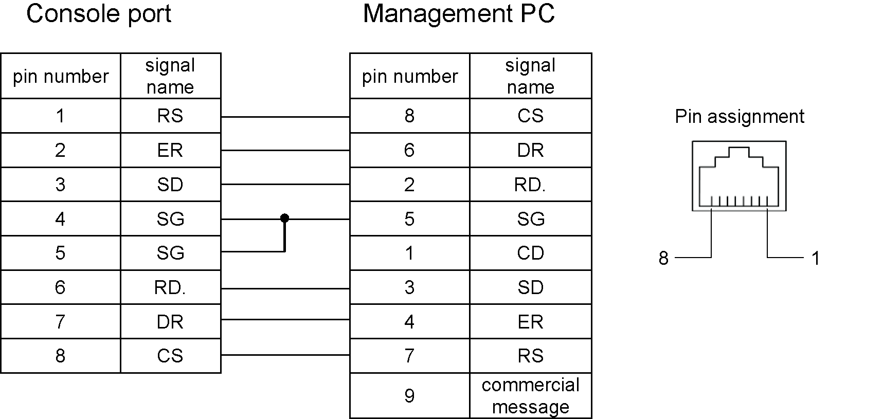
Connecting to the console port
Use standard terminal emulator software (such as PuTTY) and an RS-232C crossover cable (RJ-45 (male) - D-Sub 9-pin (female)) to connect a management PC to the FS-AX9000G-SUP CONSOLE port.
Use the following serial settings:
Baud Rate (bps) 115200, Data bits 8, Parity None, Stop bits 1, and Flow Control None
The pin assignment of the RS-232C crossover cable is shown below.
|
|
An RS-232C cable compliant with Cisco Systems' specifications can be used. Check the signal line specifications of the RS-232C cable and the management PC before use. |
Using the MGMT port
You can connect the FS-AX9000G-SUP management to your network with any appropriate Ethernet cable. The FS-AX9000G-SUP supports SSH for secure CLI access and SFTP for securely uploading firmware to or downloading files from the FS-AX9000G-SUP.
Hot swapping a supervisor in a dual-supervisor configuration
|
|
Installation and replacement of optional equipment should be performed by trained technicians or maintenance personnel. When replacing the Power Supply, install and remove the power cable. Improper handling by persons other than those mentioned above may cause fire, electric shock, or equipment failure. Improper handling of other optional devices may also cause injury or device failure. |
Do not touch the mounted components or solder surfaces of the Supervisor. When storing the Supervisor, keep it in an antistatic bag.
Remove the blank panel before adding a supervisor to a blank chassis slot. Keep the removed blank panel in a safe place.
When adding or replacing a supervisor while the chassis is powered on, use command input from the operating terminal.
-
If the supervisor to be replaced is operating, log into the supervisor CLI enter the
inactivatecommand to shut down the supervisor.If the supervisor is operating as the active supervisor, before it shuts down the standby supervisor will become the active supervisor.
-
Attach an ESD wrist strap to your wrist and to an ESD socket or to a bare metal surface on the chassis or frame.
-
When the supervisor has shut down (STATUS LED is off) completely loosen the supervisor retention screws.
-
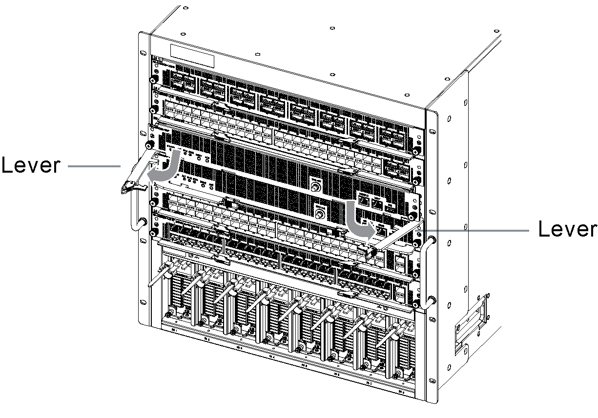
Open both levers at the same time to push the supervisor out of its slot.
When moving the levers, do not apply excessive force, but move both the left and right levers slowly and simultaneously. The Supervisor moves out of the slot about 15 mm.
-
Pull the supervisor completely out of the slot.
-
Insert the new supervisor half way into the open supervisor slot.
-
While holding the left and right levers, slowly push the levers in until they touch the device.
-
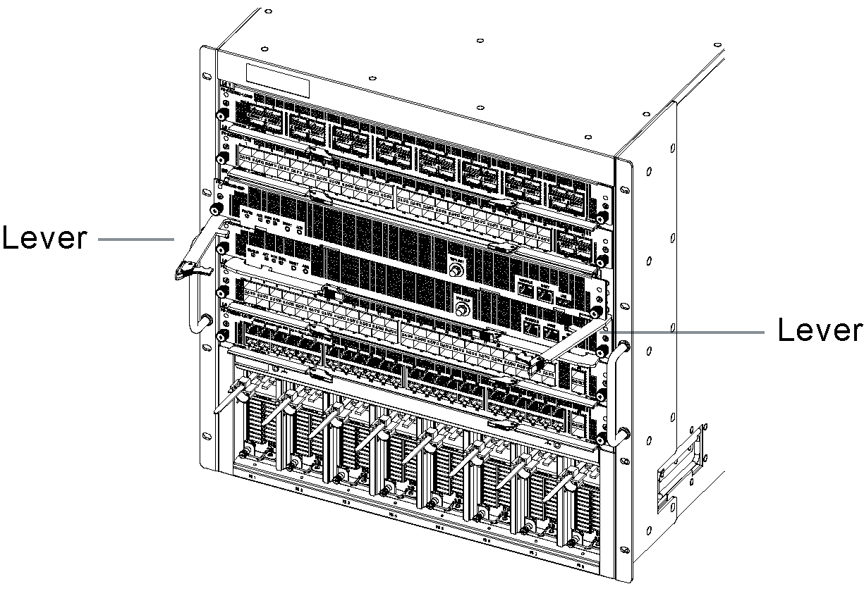
Open the levers to the angle shown below.
-
Push the supervisor all the way into the chassis slot until the levers make contact with the chassis.
-
Slowly close the levers to lock the supervisor in place in the slot.
Closing the levers aligns the supervisor in the slot and connects it to the chassis power and network connectors. When moving the levers, do not apply excessive force, but move both levers slowly and simultaneously.
-
Use a screwdriver to tighten the retention screws.
Make sure the screws are firmly secured.
Setting up new supervisors
Turn on the Supervisor (use the activate commnd).
Do one of the following depending on the supervisor configuration and operational status:
-
If the chassis contains another supervisor, synchronize the new supervisor's operational information:
-
Match the software version with the operational system (use the update software (
ppupdate) command). -
Synchronize the configuration settings with the active supervisor (use the
synchronizecommand).
-
If there is only one supervisor in a non-redundant configuration, recover the supervisor's operational information:
-
Restore operational information from a previously backed up file (use the
restorecommand). To restore the operational information, use the file backed up on a USB memory stick orftpserver.
-
When replacing both supervisors, restore the operational information of both supervisors.
-
To prevent a system switchover from occurring during the information recovery process, power down the the standby supervisor (use the
inactivatecommand). -
Restore operational information from a previously backed up file (use the
restorecommand). To restore the operational information, use the file backed up on a USB memory stick orftpserver. -
Turn on the standby supervisor (use the
activatecommand). -
Match the software version of the standby supervisor with the active supervisor (use the update software (
ppupdate) command). -
Synchronize the configuration from the active supervisor to the standby supervisor (use the
synchronizecommand).