FortiSwitch-AX9004G series schematic
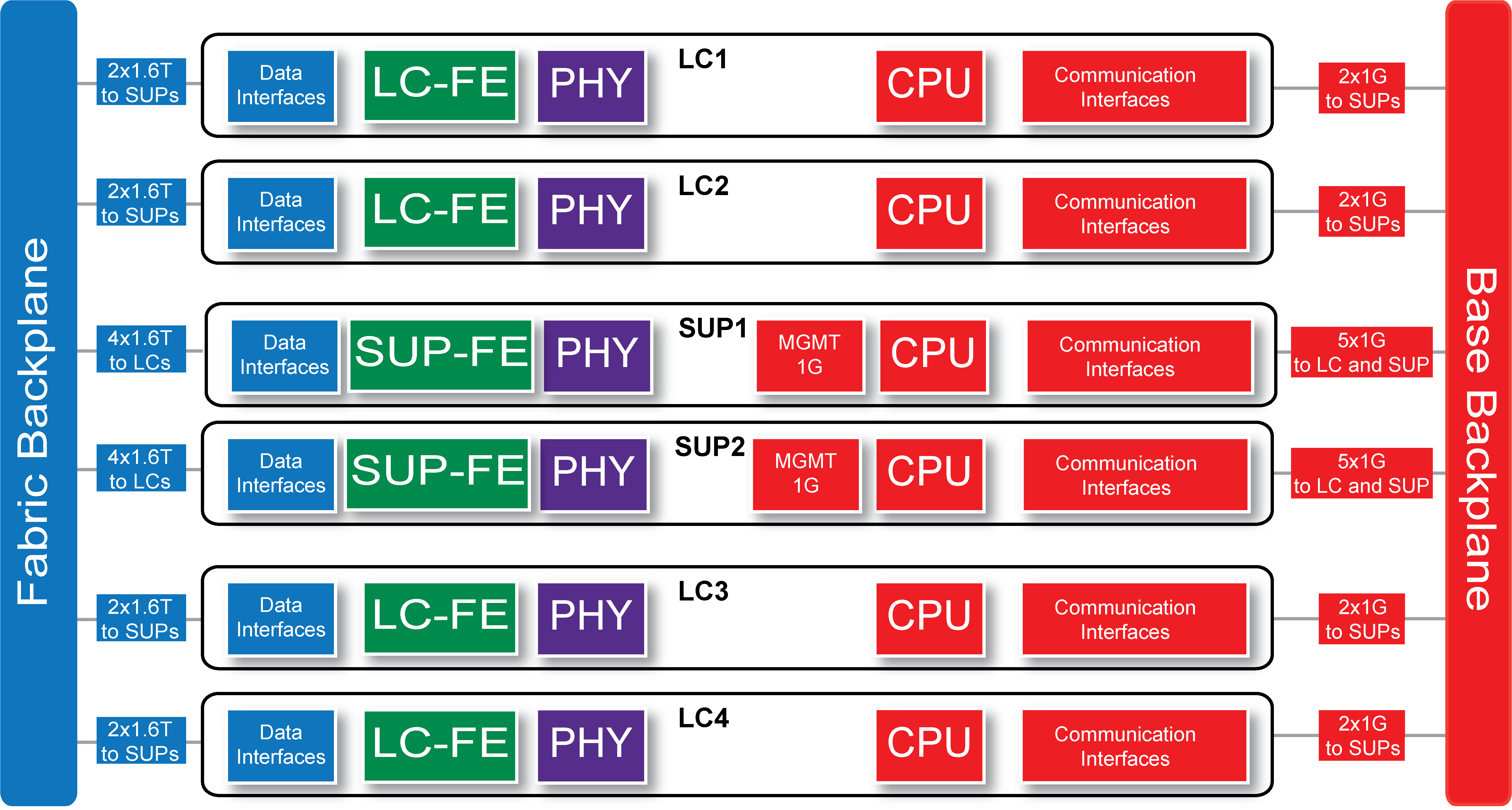
The FortiSwitch-AX9004G chassis schematic shows the communication channels between the supervisors (SUP1 and SUP2) and the line cards (LC1 to LC4).
By default, SUP1 is active and SUP2 is standby. Active refers to the SUP that is controlling the chassis. The MGMT interfaces and console ports on both SUPs are always available. Each SUP have a SUP-FE (forwarding engine) and an LC has an LC-FE (forwarding engine). These FEs support data communication between the SUP and the LCs. The FortiSwitch-AX9004G also supports communication among all SUPs and LCs. The base backplane includes 1Gbps ethernet management connections between the SUPs and the LCs.