
Configuring SD-WAN in an HA cluster using virtual VLAN switch
In this SD-WAN configuration, two FortiGates in an active-passive (A-P) HA pair are used to provide hardware redundancy. Instead of using external switches to provide a mesh network connection to the ISP routers, each FortiGate connects to an ISP and uses a virtual VLAN switch to connect to each other. Virtual VLAN switch mode allows 802.1Q VLANs to be assigned to it, and the configuration of one interface as a trunk port.
|
|
Only FortiGate models that support the virtual VLAN switch feature can be used for this solution. See Virtual VLAN switch for details. |
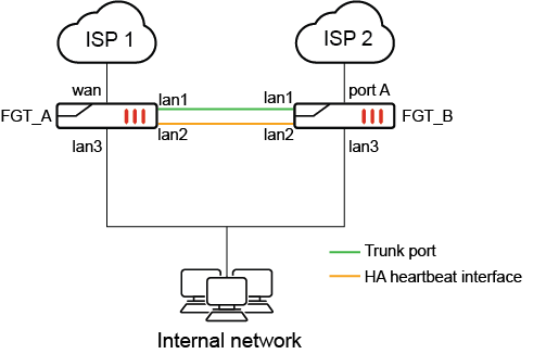
In this topology:
-
An HA cluster of two FortiGate 40Fs is used as an example
-
The lan interface is broken up into lan1, lan2 and lan3
-
lan1 is connected between FGT_A and FGT_B and designated as a virtual VLAN switch trunk port
-
lan2 is used for HA heartbeat, connecting the two FortiGates in HA
-
lan3 is connected to the internal network
-
wan is connected to ISP1 on FGT_A
-
port A is connected to ISP on FGT_B
Two VLANs are created (VLAN 10 and VLAN 20), and assigned to two VLAN switches. Each VLAN switch has the WAN interfaces (wan and port A) as its member.
When FGT_A is the primary device, it reaches ISP1 directly via the local wan interface and reaches ISP2 via the trunk port towards FGT_B. Packets are tagged/untagged as VLAN 10 as it passes through the trunk before egressing on port A on FGT_B.
When FGT_B is the primary device, it reaches ISP2 directly via the local port A interface and reaches ISP1 via the trunk port towards FGT_A. Packets are tagged/untagged as VLAN 20 as it passes through the trunk before egressing on the wan interface on FGT_A.
|
|
Using virtual VLAN switches for an SD-WAN HA configuration, as described in this example, requires fewer interfaces than the hardware switch configuration described in Configuring SD-WAN in an HA cluster using internal hardware switches A virtual VLAN switch configuration with 2 WAN connections requires 5 interfaces. With 3 WAN connections, a total of 6 interfaces are required. For the internal hardware switch solution, each WAN connection requires a corresponding hardware switch interface. With 2 WAN connections, a total of 6 interfaces are needed. With 3 WAN connections, a total of 8 interfaces are needed. |
HA failover
This is not a standard HA configuration with external switches. In the case of a device failure, one of the ISPs will no longer be available because the switch that is connected to it will be down.
For example, if FGT_A loses power, HA failover will occur and FGT_B will become the primary unit. Its connection to VLAN 10 over the trunk port will be down, so it will be unable to connect to ISP 1. Its SD-WAN SLAs will be broken, and traffic will only be routed through ISP 2.
|
|
SD-WAN SLA health checks should be used to monitor the health of each ISP. HA link monitoring will not be possible, since at least one of the WAN interfaces will be down on each FortiGate at all times. |
Configuration
In the configuration example, it is assumed HA A-P mode is already configured and FGT_A and FGT_B are in sync.
To configure the virtual VLAN switch, VLANs and interface settings in the GUI:
-
Enable Virtual VLAN switch from the GUI under the System > Settings page. In the View Settings section, enable VLAN switch mode. Click Apply.
-
Create a new VLAN switch and assign the wan interface in the GUI.
-
Go to Network > Interfaces and click Create New > Interface.
-
Enter the name ISP1
-
Set the Type to VLAN Switch.
-
Enter the VLAN ID 10.
-
Click the + and add the Interface Members. Select the interface wan.
-
Configure the Address (192.168.10.99/24) and Administrative Access settings as needed.
-
Click OK.
-
-
Repeat the same steps for a new VLAN switch and assign the port A interface in the GUI.
-
Go to Network > Interfaces and click Create New > Interface.
-
Enter the name ISP2
-
Set the Type to VLAN Switch.
-
Enter the VLAN ID 20.
-
Click the + and add the Interface Members. Select the interface ‘a’.
-
Configure the Address (192.168.20.99/24) and Administrative Access settings as needed.
-
Click OK
-
-
Designate an interface as the trunk port from the CLI:
config system interface
edit lan1
set trunk enable
next
end
To configure the virtual VLAN switch, VLANs and interface settings in the CLI:
config system global
set virtual-switch-vlan enable
end
config system virtual-switch
edit "ISP1"
set physical-switch "sw0"
set vlan 10
config port
edit "wan"
next
end
next
edit "ISP2"
set physical-switch "sw0"
set vlan 20
config port
edit "a"
next
end
next
end
config system interface
edit "ISP1"
set vdom "root"
set ip 192.168.10.99 255.255.255.0
set allowaccess ping
set type hard-switch
next
edit "ISP2"
set vdom "root"
set ip 192.168.20.99 255.255.255.0
set allowaccess ping
set type hard-switch
next
end
config system interface
edit lan1
set trunk enable
next
end
To configure SD-WAN in the GUI:
-
On the FortiGate, go to Network > SD-WAN, select the SD-WAN Zones tab, and click Create New > SD-WAN Member.
-
In the Interface dropdown, select ISP1.
-
Leave SD-WAN Zone set to virtual-wan-link.
-
Enter the Gateway address 192.168.10.1.
-
Click OK.
-
Repeat these steps to add the second interface (ISP2) with the gateway 192.168.20.1.
-
Click Apply.
-
Create a health check:
-
Go to Network > SD-WAN, select the Performance SLA tab, and click Create New.
-
Set Name to GW_HC.
-
Set Protocol to Ping and Servers to 8.8.8.8.
-
Set Participants to All SD-WAN Members.
-
Enable SLA Target and leave the default values.
-
Click OK.
-
-
Create SD-WAN rules as needed. The SLA health check can be used to determine when the ISP connections are in or out of SLA, and to failover accordingly.
-
Configure your firewall policy as needed for the virtual-wan-link SD-WAN zone.