
Overlapping subnets in IPsec occur when two or more networks involved in a VPN tunnel use the same or overlapping IP address ranges. This creates a conflict, as IPsec relies on unique network subnets to route traffic securely between them. Overlapping subnets often occur when two networks with the same IP ranges need to communicate, such as in mergers or acquisitions.
This example shows the configuration steps required to set up an IPsec VPN that enables communication between two overlapping networks located behind separate FortiGates using a route-based tunnel. Both source NAT (SNAT) and destination NAT (DNAT) are used to resolve IP conflicts.
Both the HQ and Branch FortiGates use the same overlapping internal subnet, 192.168.111.0/24. To establish communication between these networks over the IPsec tunnel, address translation is required to distinguish between the identical subnets. Without SNAT and DNAT, routing traffic between these overlapping networks would lead to conflicts, as networking devices cannot differentiate between identical IP addresses.
To resolve this issue, a unique and non-overlapping subnet is used on both FortiGates for address translation during transit.
-
On the HQ FortiGate, the IP addresses of the HQ original subnet are logically one-to-one mapped to IP address in the HQ virtual subnet of 10.1.1.0/24.
-
On the Branch FortiGate, the IP addresses of the Branch original subnet are logically one-to-one mapped to IP address in the Branch virtual subnet of 10.2.2.0/24.
The virtual subnets must be the same size as the overlapping subnet to cover the entire IP address range in the subnet and avoid network issues. The virtual subnets are used for SNAT using IP Pools and DNAT using virtual IP (VIP) configurations, ensuring that traffic originating from the overlapped subnets is translated according to the respective virtual subnets for communication.
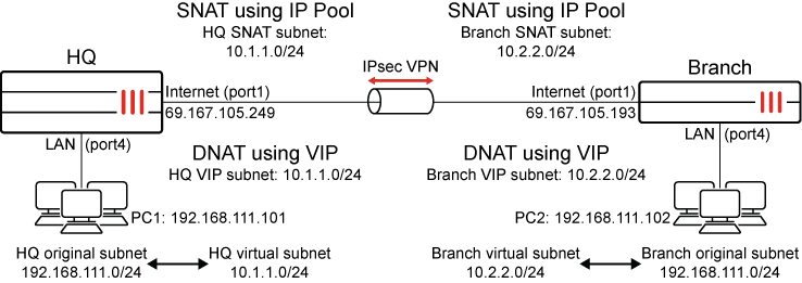
After the configuration is complete, users that are in the HQ original subnet (192.168.111.0/24) are required to the Branch virtual subnet (10.2.2.0/24) to communicate with users that are behind the Branch. Users that are in the Branch original subnet (192.168.111.0/24) are required to use the HQ virtual subnet (10.1.1.0/24) to communicate with users that are behind the HQ.
|
Source |
Destination |
Used subnet |
|---|---|---|
|
HQ |
Branch |
Branch virtual subnet (10.2.2.0/24) |
|
Branch |
HQ |
HQ virtual subnet (10.1.1.0/24) |
This ensures seamless communication across the IPsec tunnel while resolving the challenges posed by overlapping subnets.
HQ FortiGate configuration
To configure IPsec VPN:
-
Go to VPN > VPN Tunnels and click on Create New > Custom IPsec tunnel.
-
Set the Name, such as HQtoBranchVPN.
-
Configure the Network settings:
Field
Value
IP version
IPv4
Remote gateway
Static IP address
IP address
69.167.105.193
Interface
Internet (port1)
Transport
UDP
-
Leave the remaining Network settings as their default values.
-
Configure the Authentication settings:
Field
Value
Method
Pre-shared Key
Pre-shared key
Enter a suitable key.
The same pre-shared key must be configured on the Branch FortiGate.
-
Leave the remaining Authentication settings as their default values.
-
Leave the Phase 1 proposal settings as their default values.
-
Configure the Phase 2 selectors settings:
-
In the table, click Create New.
-
Configure the new phase 2 selector:
Field
Value
Name
HQtoBranchVPN
Local address
Subnet Address
10.1.1.0/24
Remote address
Subnet Address
10.2.2.0/24
Auto-negotiate
(Optional) Enable

Only traffic matching the subnets specified in the Local address and Remote address fields in the Phase 2 configuration can pass through the IPsec tunnel.
-
Outgoing traffic exiting through the IPsec tunnel is first matched against a firewall policy, then Source NAT (if configured) is applied, and finally, is checked against the traffic selectors in the IPsec tunnel settings.
-
Incoming traffic on IPsec tunnel is first evaluated against the traffic selectors, then matched to a firewall policy, and finally, DNAT (if configured) is applied.
-
-
Leave the remaining settings as their default values and click OK.
-
-
Click OK.
To configure static routes:
-
Go to Network > Static Routes and click Create New.
-
Configure the static route for the Branch virtual subnet:
Field
Value
Destination
Subnet
10.2.2.0/24
Interface
HQtoBranchVPN (the IPsec tunnel interface)
Administrative Distance
10
Status
Enabled
-
Click OK.
-
Create a second static route with the same Destination that uses the blackhole interface.
This is a best practice for route-based IPsec VPN tunnels because it ensures that traffic for the remote FortiGate's subnet is not sent using the default route in the event that the IPsec tunnel goes down and is instead sent to the blackhole.
Field
Value
Destination
Subnet
10.2.2.0/24
Interface
Blackhole
Administrative Distance
254
Status
Enable
To configure the address objects:
-
Go to Policy & Objects > Addresses and select Address.
-
Click Create new and configure an address object for HQ original subnet:
Field
Value
Name
HQ original subnet
Interface
Any
Type
Subnet
IP/Netmask
192.168.111.0/24
Routing configuration
Disable
-
Click OK.
-
Click Create new again and configure an address object for Branch virtual subnet:
Field
Value
Name
Branch virtual subnet
Interface
Any
Type
Subnet
IP/Netmask
10.2.2.0/24
Routing configuration
Disable
-
Click OK
To configure the IP pool for SNAT:
-
Go to Policy & Objects > IP Pools and click Create new.
-
Configure the dynamic IP pool:
Field
Value
Name
HQ SNAT subnet
Type
Fixed Port Range
External IP Range
10.1.1.1-10.1.1.254
Internal IP Range
192.168.111.1-192.168.111.254
-
Leave the remaining settings as their default values and click OK.
To configure the VIP for DNAT:
-
Go to Policy & Objects > Virtual IPs and select the Virtual IP tab.
-
Click Create new.
-
Configure the virtual IP:
Field
Value
Name
HQ VIP subnet
Type
Static NAT
External IP address/range
10.1.1.1-10.1.1.254
Map to IPv4 address/range
192.168.111.1
-
Click OK.
To configure the firewall policies:
-
Go to Policy & Objects > Firewall Policy and click Create New.
-
Configure the policy to allow traffic to flow from the HQ original subnet to the Branch virtual subnet and to perform SNAT:
Field
Value
Name
HQ to Branch
Incoming interface
LAN (port4)
Outgoing interface
HQtoBranchVPN
Source
HQ original subnet
Destination
Branch virtual subnet
Service
ALL
NAT
Enable
IP pool configuration
Use Dynamic IP Pool
HQ SNAT subnet IP
-
Configure the remaining settings as needed, then click OK.
-
Click Create New again and configure the policy to allow traffic to flow from the Branch virtual subnet to the HQ original subnet and to perform DNAT:
Field
Value
Name
Branch to HQ
Incoming interface
HQtoBranchVPN
Outgoing interface
LAN (port4)
Source
Branch virtual subnet
Destination
HQ VIP subnet (the virtual IP/server to perform DNAT)
Service
ALL
NAT
Disable
-
Configure the remaining settings as needed, then click OK.
Branch FortiGate configuration
To configure IPsec VPN:
-
Go to VPN > VPN Tunnels and click on Create New > Custom IPsec tunnel.
-
Set the Name, such as BranchtoHQVPN.
-
Configure the Network settings:
Field
Value
IP version
IPv4
Remote gateway
Static IP address
IP address
69.167.105.249
Interface
Internet (port1)
Transport
UDP
-
Leave the remaining Network settings as their default values.
-
Configure the Authentication settings:
Field
Value
Method
Pre-shared Key
Pre-shared key
Enter a suitable key.
The same pre-shared key must be configured on the HQ FortiGate.
-
Leave the remaining Authentication settings as their default values.
-
Leave the Phase 1 proposal settings as their default values.
-
Configure the Phase 2 selectors settings:
-
In the table, click Create New.
-
Configure the new phase 2 selector:
Field
Value
Name
BranchtoHQVPN
Local address
Subnet Address
10.2.2.0/24
Remote address
Subnet Address
10.1.1.0/24
Auto-negotiate
(Optional) Enable
Only traffic matching the subnets specified in the Local address and Remote address fields in the Phase 2 configuration can pass through the IPsec tunnel.
-
Outgoing traffic exiting through the IPsec tunnel is first matched against a firewall policy, then Source NAT (if configured) is applied, and finally, is checked against the traffic selectors in the IPsec tunnel settings.
-
Incoming traffic on IPsec tunnel is first evaluated against the traffic selectors, then matched to a firewall policy, and finally, DNAT (if configured) is applied.
-
-
Leave the remaining settings as their default values and click OK.
-
-
Click OK.
To configure static routes:
-
Go to Network > Static Routes and click Create New.
-
Configure the static route for the Branch virtual subnet:
Field
Value
Destination
Subnet
10.1.1.0/24
Interface
BranchtoHQVPN (the IPsec tunnel interface)
Administrative Distance
10
Status
Enabled
-
Click OK.
-
Create a second static route with the same Destination that uses the blackhole interface.
This is a best practice for route-based IPsec VPN tunnels because it ensures that traffic for the remote FortiGate's subnet is not sent using the default route in the event that the IPsec tunnel goes down and is instead sent to the blackhole.
Field
Value
Destination
Subnet
10.1.1.0/24
Interface
Blackhole
Administrative Distance
254
Status
Enable
To configure the address objects:
-
Go to Policy & Objects > Addresses and select Address.
-
Click Create new and configure an address object for HQ original subnet:
Field
Value
Name
Branch original subnet
Interface
Any
Type
Subnet
IP/Netmask
192.168.111.0/24
Routing configuration
Disable
-
Click OK.
-
Click Create new again and configure an address object for Branch virtual subnet:
Field
Value
Name
HQ virtual subnet
Interface
Any
Type
Subnet
IP/Netmask
10.1.1.0/24
Routing configuration
Disable
-
Click OK
To configure the IP pool for SNAT:
-
Go to Policy & Objects > IP Pools and click Create new.
-
Configure the dynamic IP pool:
Field
Value
Name
Branch SNAT subnet
Type
Fixed Port Range
External IP Range
10.2.2.1-10.2.2.254
Internal IP Range
192.168.111.1-192.168.111.254
-
Leave the remaining settings as their default values and click OK.
To configure the VIP for DNAT:
-
Go to Policy & Objects > Virtual IPs and select the Virtual IP tab.
-
Click Create new.
-
Configure the virtual IP:
Field
Value
Name
Branch VIP subnet
Type
Static NAT
External IP address/range
10.2.2.1-10.2.2.254
Map to IPv4 address/range
192.168.111.1
-
Click OK.
To configure the firewall policies:
-
Go to Policy & Objects > Firewall Policy and click Create New.
-
Configure the policy to allow traffic to flow from the HQ original subnet to the Branch virtual subnet and to perform SNAT:
Field
Value
Name
Branch to HQ
Incoming interface
LAN (port4)
Outgoing interface
BranchtoHQVPN
Source
Branch original subnet
Destination
HQ virtual subnet
Service
ALL
NAT
Enable
IP pool configuration
Use Dynamic IP Pool
Branch SNAT subnet IP
-
Configure the remaining settings as needed, then click OK.
-
Click Create New again and configure the policy to allow traffic to flow from the Branch virtual subnet to the HQ original subnet and to perform DNAT:
Field
Value
Name
HQ to Branch
Incoming interface
BranchtoHQVPN
Outgoing interface
LAN (port4)
Source
HQ virtual subnet
Destination
Branch VIP subnet (the virtual IP/server to perform DNAT)
Service
ALL
NAT
Disable
-
Configure the remaining settings as needed, then click OK.
Verification
To verify the status of IPsec tunnel in the GUI:
-
On either FortiGate, go to Dashboard > Network and expand the IPsec widget.
-
The tunnels should be up on both FortiGates. If you did not enable Auto-negotiate in the IPsec VPN settings, you may have to select the tunnel and click Bring Up.
To verify the status of IPsec tunnel in the CLI:
-
Verify the status of Phase 1:
Branch # diagnose vpn ike gateway list name BranchtoHQVPN
vd: root/0
name: BranchtoHQVPN
version: 2
interface: port1 3
addr: 10.100.66.99:4500 -> 69.167.105.249:4500
tun_id: 69.167.105.249/::69.167.105.249
remote_location: 0.0.0.0
network-id: 0
transport: UDP
created: 58s ago
peer-id: 10.100.66.99
peer-id-auth: no
nat: me peer
pending-queue: 0
PPK: no
IKE SA: created 1/1  established 1/1  time 10/10/10 ms
IPsec SA: created 1/1  established 1/1  time 10/10/10 ms

  id/spi: 5 8d6f155741b90831/54940957144cdd82
  direction: initiator
  ...
  peer-id: 10.100.66.99
-
Verify the status of Phase 2:
Branch # diagnose vpn tunnel list name BranchtoHQVPN
list ipsec tunnel by names in vd 0
------------------------------------------------------
name=BranchtoHQVPN ver=2 serial=1 10.100.66.99:4500->69.167.105.249:4500 nexthop=10.100.66.1 tun_id=69.167.105.249 tun_id6=::69.167.105.249 status=up dst_mtu=1200 weight=1
bound_if=3 real_if=3 lgwy=static/1 tun=intf mode=auto/1 encap=none/552 options[0228]=npu frag-rfc  run_state=0 role=primary accept_traffic=1 overlay_id=0

proxyid_num=1 child_num=0 refcnt=6 ilast=8103 olast=8103 ad=/0
stat: rxp=0 txp=0 rxb=0 txb=0
dpd: mode=on-demand on=1 status=ok idle=20000ms retry=3 count=0 seqno=0
natt: mode=keepalive draft=0 interval=10 remote_port=4500
fec: egress=0 ingress=0
proxyid=BranchtoHQVPN proto=0 sa=1 ref=2 serial=2 auto-negotiate
  src: 0:10.2.2.0-10.2.2.255:0
  dst: 0:10.1.1.0-10.1.1.255:0
  SA:  ref=3 options=38203 type=00 soft=0 mtu=1134 expire=42550/0B replaywin=2048
       seqno=1 esn=0 replaywin_lastseq=00000000 qat=0 rekey=0 hash_search_len=1
  life: type=01 bytes=0/0 timeout=42899/43200
  dec: spi=617afb8e esp=aes key=16 c930949dfb07586bf59621f7371bcf6d
       ah=sha1 key=20 53ef18c8d261ba13ca6faa130f1bcbb3eb9987c8
  enc: spi=03ec3c88 esp=aes key=16 88f4d37c477b5198c75ecfe19b3053c0
       ah=sha1 key=20 5bbaa833a7e099dc49557877f0023267db2f08ac
  dec:pkts/bytes=0/0, enc:pkts/bytes=0/0
  npu_flag=00 npu_rgwy=69.167.105.249 npu_lgwy=10.100.66.99 npu_selid=2 dec_npuid=0 enc_npuid=0
Note that the protected subnet in the IPsec tunnel are the virtual subnets for Branch and HQ, respectively.
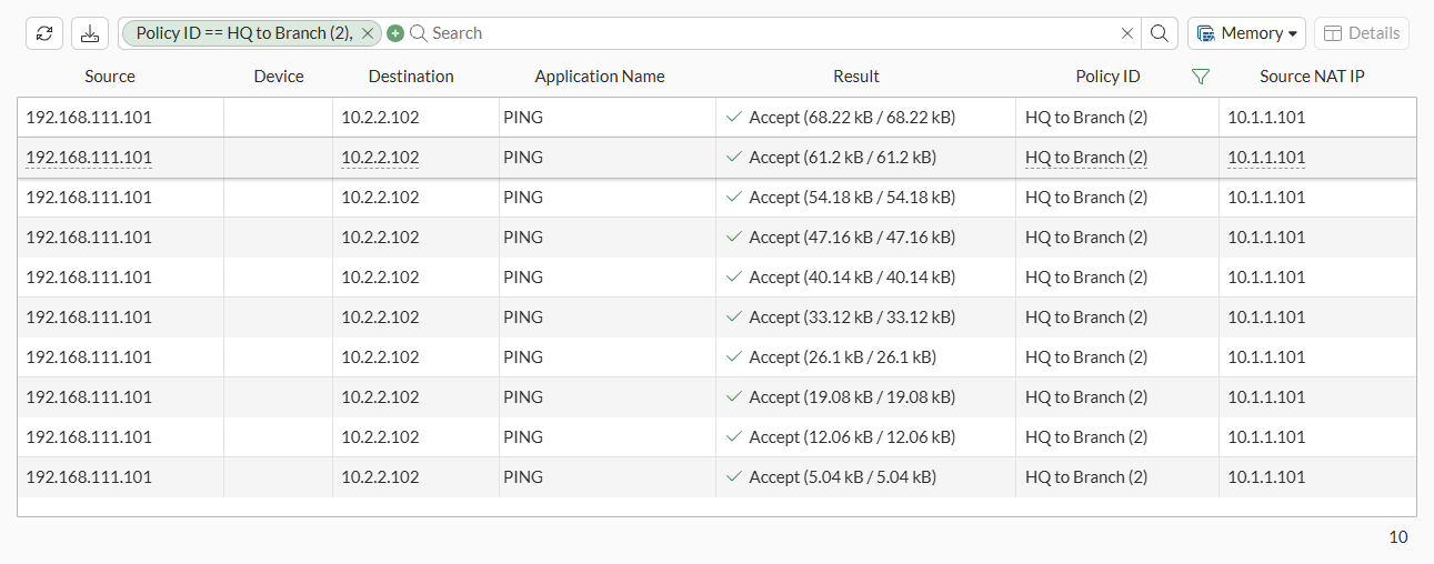
To verify the traffic flow from PC1 to PC2:
-
From a PC in the HQ network (PC1, 192.168.111.101), ping a PC in the Branch network (PC2, 192.168.111.102) using the virtual IP of PC2, 10.2.2.102.
The ping should be successful.
C:\>ping 10.2.2.102

Pinging 10.2.2.102 with 32 bytes of data:
Reply from 10.2.2.102: bytes=32 times=10ms TTL=126
Reply from 10.2.2.102: bytes=32 times=3ms TTL=126
Reply from 10.2.2.102: bytes=32 times=3ms TTL=126
Reply from 10.2.2.102: bytes=32 times=3ms TTL=126

Ping statistics for 10.2.2.102:
    Packets: Sent = 4, Received = 4, Lost = 0 (0% loss),
Approximate round trip times in milli-seconds:
    Minimum = 3ms, Maximum = 10ms, Average = 4ms
To verify the traffic flow from PC1 to PC2 in the GUI:
-
On either FortiGate, go to Log & Report > Forward Traffic.
-
Filter the content using the search bar and add the required columns to see the logs.
|
|
To make sure that the logs are collected and shown under Forward Traffic, set Log Allowed Traffic to All Sessions in the corresponding firewall policy configured under Policy & Objects > Firewall Policy. |
To verify the traffic flow from PC1 to PC2 in the CLI:
-
Verify the SNAT operation for traffic flowing from PC1 to PC2 on HQ:
-
Using sniffer trace:
HQ # diagnose sniffer packet any 'icmp' 4 10
Using Original Sniffing Mode
interfaces=[any]
filters=[icmp]
6.141932 port4 in 192.168.111.101 -> 10.2.2.102: icmp: echo request
6.144532 HQtoBranchVPN out 10.1.1.101 -> 10.2.2.102: icmp: echo request
6.149731 HQtoBranchVPN in 10.2.2.102 -> 10.1.1.101: icmp: echo reply
6.149770 port4 out 10.2.2.102 -> 192.168.111.101: icmp: echo reply
-
Using session table:
HQ # diagnose sys session filter proto 1
HQ # diagnose sys session list
session info: proto=1 proto_state=00 duration=1 expire=58 timeout=0 refresh_dir=both flags=00000000 socktype=0 sockport=0 av_idx=0 use=3
origin-shaper=
reply-shaper=
per_ip_shaper=
class_id=0 ha_id=0 policy_dir=0 tunnel=/ tun_id=69.167.105.193/0.0.0.0 vlan_cos=0/255
state=may_dirty
statistic(bytes/packets/allow_err): org=60/1/1 reply=60/1/1 tuples=2
tx speed(Bps/kbps): 31/0 rx speed(Bps/kbps): 31/0
orgin->sink: org pre->post, reply pre->post dev=6->16/16->6 gwy=69.167.105.193/0.0.0.0
hook=post dir=org act=snat 192.168.111.101:1->10.2.2.102:8(10.1.1.101:5437)
hook=pre dir=reply act=dnat 10.2.2.102:5437->10.1.1.101:0(192.168.111.101:1)
misc=0 policy_id=2 pol_uuid_idx=15849 auth_info=0 chk_client_info=0 vd=0
serial=00008136 tos=ff/ff app_list=0 app=0 url_cat=0
rpdb_link_id=00000000 ngfwid=n/a
npu_state=0x000100
no_ofld_reason:  npu-flag-off
total session: 1
-
-
Verify the DNAT operation for traffic flowing from PC1 to PC2 on Branch:
-
Using sniffer trace:
Branch # diagnose sniffer packet any 'icmp' 4 10
Using Original Sniffing Mode
interfaces=[any]
filters=[icmp]
5.738981 BranchtoHQVPN in 10.1.1.101 -> 10.2.2.102: icmp: echo request
5.739058 port4 out 10.1.1.101 -> 192.168.111.102: icmp: echo request
5.740026 port4 in 192.168.111.102 -> 10.1.1.101: icmp: echo reply
5.740068 BranchtoHQVPN out 10.2.2.102 -> 10.1.1.101: icmp: echo reply
-
Using session table:
Branch # diagnose sys session filter proto 1
Branch # diagnose sys session list
session info: proto=1 proto_state=00 duration=3 expire=56 timeout=0 refresh_dir=both flags=00000000 socktype=0 sockport=0 av_idx=0 use=3
origin-shaper=
reply-shaper=
per_ip_shaper=
class_id=0 ha_id=0 policy_dir=0 tunnel=/ tun_id=0.0.0.0/69.167.105.249 vlan_cos=0/255
state=may_dirty
statistic(bytes/packets/allow_err): org=60/1/1 reply=60/1/1 tuples=2
tx speed(Bps/kbps): 15/0 rx speed(Bps/kbps): 15/0
orgin->sink: org pre->post, reply pre->post dev=16->6/6->16 gwy=0.0.0.0/69.167.105.249
hook=pre dir=org act=dnat 10.1.1.101:5437->10.2.2.102:8(192.168.111.102:5437)
hook=post dir=reply act=snat 192.168.111.102:5437->10.1.1.101:0(10.2.2.102:5437)
misc=0 policy_id=3 pol_uuid_idx=15862 auth_info=0 chk_client_info=0 vd=0
serial=00005b94 tos=ff/ff app_list=0 app=0 url_cat=0
rpdb_link_id=00000000 ngfwid=n/a
npu_state=0x000100
no_ofld_reason:  npu-flag-off
total session: 1
-
For more information on running sniffer trace, see Performing a sniffer trace or packet capture. For more information about using session table, see Using a session table.