
FGR-70F/FGR-70F-3G4G GPIO/DIO module
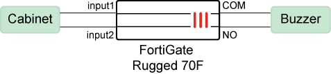
FortiGate Rugged 70F and FortiGate Rugged 70F-3G4G include a general purpose input output (GPIO) module, also known as a digital I/O (DIO) module. This module activates a digital output when triggered by a change in any digital input. For example, the digital input can be connected to a cabinet door to monitor the open/close status or low/high voltage status, and the output can be connected to a buzzer. When the DIO module detects a change from open to closed or a voltage change from low to high, it triggers the buzzer.
CLI for configuring DIO module alarms is available only on FortiGate Rugged 70F and FortiGate Rugged 70F-3G4G devices.
Use the config system digital-io command to configure the input status for the DIO module to monitor:
config system digital-io
    set input1-detection-mode {default | voltage}
    set input2-detection-mode {default | voltage}
    set output-keep-last-state {enable | disable}
end
|
set input1-detection-mode {default | voltage} |
Configure the input mode:
|
|
set output-keep-last-state {enable | disable} |
Enable/disable FortiGate to keep the alarm status after a reboot. |
Use the execute digital-io set-output command to configure the output mode when an alarm is triggered, namely, the state of the normally closed to common (NC_COM) output and the normally open to common (NO_COM) output:
# execute digital-io set-output
alternating     Alternates between default and opposite.
default         NC_COM=closed and NO_COM=open.
opposite        NC_COM=open and NO_COM=closed.
Use the diagnose sys digital-io state command to check the input and output status reported by the DIO module:
# diagnose sys digital-io state
Input1:    mode=default(open/closed) and state=open.
Input2:    mode=voltage(low/high) and state=low.
Output:    state=default, NO_COM=open, and NC_COM=closed.
output-keep-last-state: enable
Commands are also available to trigger SNMP traps and automation stitches for the DIO module. See SNMP traps and automation-stitch notifications for DIO module for more information.
For more information about the DIO module, see the FortiGate Rugged 70F Series QuickStart Guide and the Technical Tip: Overview of the Digital Input/Output (DIO) Module in FortiGate Rugged 70F Series community article.
Example
In this example, a FortiGate Rugged 70F is configured to monitor the open/close and low/high voltage status of a cabinet door, and the output is connected to a buzzer. When the status of the cabinet door changes, FortiGate triggers the buzzer
To configure the DIO module alarm:
-
Configure the input-detection mode:
In this example, the input-detection mode for input1 is set to
defaultand input2 is set tovoltage, and the last output state is retained if FortiGate reboots.config system digital-io set input1-detection-mode default set input2-detection-mode voltage set output-keep-last-state enable end -
Configure the output mode:
In this example, the output is set to
default. When triggered, the output is in a default state with the normally open to common (NO_COM) output being open, and the normally closed to common (NC_COM) output being closed. The output is triggered when the DIO module detects a change in the status of the inputs or detects an alarm event.# execute digital-io set-output default
-
View the input/output status being reported by the DIO module:
In this example, the default state of
Input1isopen, and the default state ofInput2islowvoltage, which means the cabinet door is open, and the voltage is low.# diagnose sys digital-io state Input1: mode=default(open/closed), state=open Input2: mode=voltage(low/high), state=low Output: state=default, NO_COM=open, NC_COM=closed output-keep-last-state: enable
-
Close the cabinet door.
-
View the input/output status being reported by the DIO module:
The state of
Input1has changed toclosed, and the state ofInput2has changed tohighvoltage.# diagnose sys digital-io state Input1: mode=default(open/closed), state=closed Input2: mode=voltage(low/high), state=high Output: state=default, NO_COM=open, NC_COM=closed output-keep-last-state: enable
The change in state triggers the buzzer.