
Cisco GRE-over-IPsec VPN
This is a sample configuration of a FortiGate VPN that is compatible with Cisco-style VPNs that use GRE in an IPsec tunnel. Cisco products with VPN support often use the GRE protocol tunnel over IPsec encryption. Cisco VPNs can use either transport mode or tunnel mode IPsec.
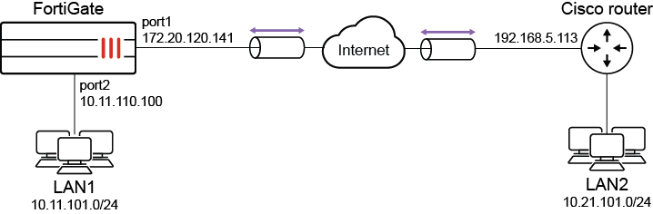
Topology
In this example, LAN1 users are provided with access to LAN2.
Configuring the FortiGate
There are five steps to configure GRE-over-IPsec with a FortiGate and Cisco router:
- Enable overlapping subnets.
- Configure a route-based IPsec VPN on the external interface.
- Configure a GRE tunnel on the virtual IPsec interface.
- Configure security policies.
- Configure the static route.
Enabling overlapping subnets
Overlapping subnets are required because the IPsec and GRE tunnels will use the same addresses. By default, each FortiGate network interface must be on a separate network. This configuration assigns an IPsec tunnel endpoint and the external interface to the same network.
To enable overlapping subnets:
config system settings
    set allow-subnet-overlap enable
    next
end
Configuring a route-based IPsec VPN
A route-based VPN that use encryption and authentication algorithms compatible with the Cisco router is required. Pre-shared key authentication is used in this configuration.
To configure route-based IPsec in the GUI:
- Go to VPN > IPsec Wizard and select the Custom template.
- Enter the tunnel name (tocisco) and click Next.
- Enter the following:
Remote Gateway
Static IP Address
IP Address
Cisco router public interface (192.168.5.113)
Interface
FortiGate public interface (172.20.120.141)
Authentication Method
Pre-shared Key
Pre-shared Key
Entry must match the pre-shared key on the Cisco router
Mode
Main (ID Protection)
Phase 1 Proposal
3DES-SHA1, AES128-SHA1 (at least one proposal must match the settings on the Cisco router)
Local Address
GRE local tunnel endpoint IP address (172.20.120.141)
Remote Address
GRE remote tunnel endpoint IP address (192.168.5.113)
Phase 2 Proposal
3DES-MD5 (at least one proposal must match the settings on the Cisco router)
Local Port
0
Remote Port
0
Protocol
47
- Click OK.
- If the Cisco router is configured to use transport mode IPsec, configure transport mode on the FortiGate:
config vpn phase2-interface
    edit tocisco_p2
        set encapsulation transport-mode
    next
end
To configure route-based IPsec in the CLI:
config vpn ipsec phase1-interface
    edit tocisco
        set interface port1
        set proposal 3des-sha1 aes128-sha1
        set remote-gw 192.168.5.113
        set psksecret xxxxxxxxxxxxxxxx
    next
end
config vpn ipsec phase2-interface
edit tocisco_p2
set phase1name tocisco
set proposal 3des-md5
set encapsulation [tunnel-mode | transport-mode]
set protocol 47
set src-addr-type ip
set dst-start-ip 192.168.5.113
set src-start-ip 172.20.120.141
next
end
To add the IPsec tunnel end addresses:
config system interface
    edit tocisco
        set ip 172.20.120.141 255.255.255.255
        set remote-ip 192.168.5.113
    next
end
Configuring the GRE tunnel
The local gateway and remote gateway addresses must match the local and remote gateways of the IPsec tunnel. The GRE tunnel runs between the virtual IPsec public interface on the FortiGate unit and the Cisco router.
To configure the GRE tunnel:
config system gre-tunnel
    edit gre1
        set interface tocisco
        set local-gw 172.20.120.141
        set remote-gw 192.168.5.113
        set keepalive-interval <integer>
        set keepalive-failtimes <integer>
    next
end
The Cisco router configuration requires an address for its end of the GRE tunnel, so you need to add the tunnel end addresses.
To add the tunnel end addresses:
config system interface
    edit gre1
        set ip 10.0.1.1 255.255.255.255
        set remote-ip 10.0.1.2
    next
end
Configuring the security policies
Two sets of security policies are required:
- Policies to allow traffic to pass in both directions between the GRE virtual interface and the IPsec virtual interface.
- Policies to allow traffic to pass in both directions between the protected network interface and the GRE virtual interface.
To configure security policies in the GUI:
- Go to Policy & Objects > Firewall Policy and click Create New.
- Enter the following to allow traffic between the protected network and the GRE tunnel:
Name
LANtoGRE
Incoming Interface
Interface that connects to the private network behind the FortiGate (port2)
Outgoing Interface
GRE tunnel virtual interface (gre1)
Source
All
Destination
All
Action
ACCEPT
NAT
Disable
- Click OK.
- Create a new policy and enter the following to allow traffic between the GRE tunnel and the protected network:
Name
GREtoLAN
Incoming Interface
GRE tunnel virtual interface (gre1)
Outgoing Interface
Interface that connects to the private network behind the FortiGate (port2)
Source
All
Destination
All
Action
ACCEPT
NAT
Disable
- Click OK.
- Create a new policy and enter the following to allow traffic between the GRE virtual interface and the IPsec virtual interface:
Name
GREtoIPsec
Incoming Interface
GRE tunnel virtual interface (gre1)
Outgoing Interface
Virtual IPsec interface (tocisco)
Source
All
Destination
All
Action
ACCEPT
NAT
Disable
- Click OK.
- Create a new policy and enter the following to allow traffic between the IPsec virtual interface and the GRE virtual interface:
Name
IPsectoGRE
Incoming Interface
Virtual IPsec interface (tocisco)
Outgoing Interface
GRE tunnel virtual interface (gre1)
Source
All
Destination
All
Action
ACCEPT
NAT
Disable
- Click OK.
To configure security policies in the CLI:
config firewall policy
    edit 1
        set name LANtoGRE
        set srcintf port2
        set dstintf gre1
        set srcaddr all
        set dstaddr all
        set action accept
        set schedule always
        set service ALL
    next
    edit 2
        set name GREtoLAN
        set srcintf gre1
        set dstintf port2
        set srcaddr all
        set dstaddr all
        set action accept
        set schedule always
        set service ALL
    next
    edit 3
        set name GREtoIPsec
        set srcintf gre1
        set dstintf tocisco
        set srcaddr all
        set dstaddr all
        set action accept
        set schedule always
        set service ALL
    next
    edit 4
        set name IPsectoGRE
        set srcintf tocisco
        set dstintf gre1
        set srcaddr all
        set dstaddr all
        set action accept
        set schedule always
        set service ALL
    next
end
Configuring routing
to direct traffic destined for the network behind the Cisco router into the GRE-over-IPsec tunnelTraffic destined for the network behind the Cisco router must be routed to the GRE tunnel. To do this, create a static route
To create the static route in the GUI:
- Go to Network > Static Routes and click Create New.
- Enter the following:
Destination
IP and netmask for the network behind the Cisco router (10.21.101.0 255.255.255.0)
Interface
GRE tunnel virtual interface (gre1)
Administrative Distance
Leave the default setting
- Click OK.
To create the static route in the CLI:
config router static
    edit 0
        set device gre1
        set dst 10.21.101.0 255.255.255.0
    next
end
Configuring the Cisco router
For more information, refer to Configuring and verifying a GRE over IPsec tunnel in the Fortinet Knowledge Base.
|
|
In this type of deployment where you configure GRE over IPsec VPN, NP7 offloading is not natively supported, even though it is supported individually for GRE and for IPsec. To workaround this, configure two separate VDOMs where one performs IPsec tunneling and the other performs GRE encapsulation. For more information, see the following KB: Technical Tip: GRE + IPSec not supported for NP7 offloading. |