


SSIDs for Authorized Users with WPA2/WPA3 Enterprise Security Mode
For main campus users who can be authenticated against a RADIUS database, choose WPA2 Enterprise or WPA3 Enterprise. This section continues the SSID configuration steps from Configuring SSIDs/WLANs
- The interface settings—name, IP address, DHCP Server are already set.
- The SSID name was entered previously.
-
Select a Security mode, either WPA2 Enterprise or WPA3 Enterprise.
The Authentication menu appears.
-
Select RADIUS Server and in the drop-down box, click Create.

The New RADIUS Server screen appears.
-
In the New RADIUS Server screen:
-
Give the server a Name.
-
If necessary, specify the Authentication method.
-
Default will negotiate PAP, MSCHAP_v2, and CHAP in that order.
-
-
Enter the IP Address of the RADIUS server.
-
Enter the shared Secret.

-
You can test connection status by clicking the Test Connectivity.
-
Click OK.
-
-
Ensure that the new server is selected in Security Mode Settings and click OK to save the new SSID.
You can see your new SSID from the SSID page.
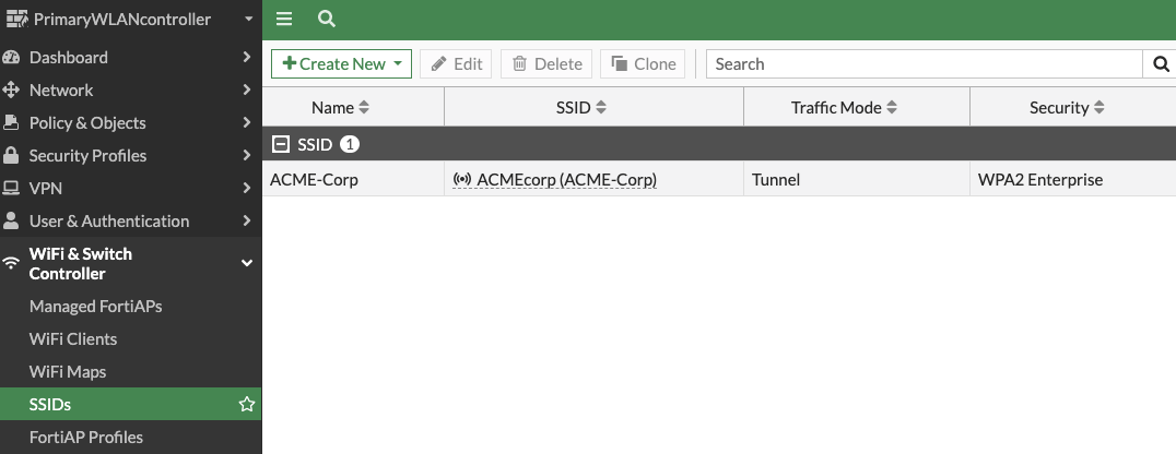
Add Firewall Policies for the Authorized Users SSID
The APs are now broadcasting the authenticated user SSID and clients can connect to the WLAN, but the traffic is isolated to the FortiGate WiFi Controller. The Fortinet Security Driven Networking model allows only explicitly allowed traffic. Firewall policies must be added to allow Internet or other network access.
-
Go to Policy & Objects > Firewall Policy.
-
Click Create New.
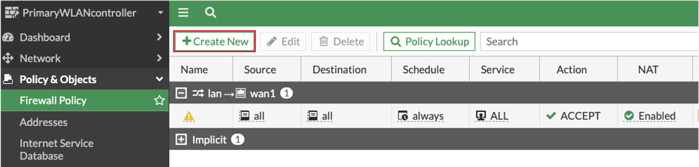
The New Policy screen appears.
- Enter a Name for the policy.
- The Incoming Interface is the WLAN defined earlier. As a new interface, the FortiGate WiFi Controller created an address object automatically.
- Following the above example configurations, the outgoing interface is the WLAN-uplink interface.
-
For simplicity, configure the Source, Destination, and Service fields as all.
- Leave the other fields with the default settings.
-
Ensure that NAT is enabled.
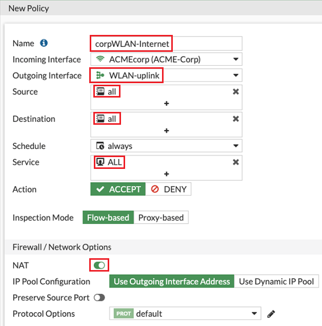
-
When you are finished, click OK.
Now Wi-Fi traffic can reach the upstream Internet gateway. This is a very simple, single rule Firewall Policy set. But keep in mind, the WiFi Controller is a full featured Next Generation Firewall (NGFW) and can work in conjunction with any upstream firewall, regardless of vendor. See other FortiGate documentation at https://docs.fortinet.com/product/fortigate.