
Layer 4 Server Load Balancing for IPsec VPN Hubs in a Hub-and-Spoke Topology
In high-availability IPsec VPN deployments, Layer 4 (L4) server load balancing enables efficient and scalable traffic distribution by inspecting packet headers at the transport layer (TCP/UDP) without processing application-layer content. FortiADC supports L4 Virtual Servers that operate transparently, forwarding packets to backend servers based on source/destination IPs and ports, using methods such as Destination NAT (DNAT) and load-balancing algorithms.
This use case demonstrates how to configure FortiADC to load balance IPsec VPN traffic from multiple spoke sites to multiple hub routers using a Layer 4 Virtual Server. The configuration leverages DNAT to preserve the illusion of a single, consistent tunnel destination (e.g., 2000:2000::254) for all spokes, while distributing traffic to different backend routers behind FortiADC.
This approach is ideal for hub-and-spoke Auto-Discovery VPN (ADVPN) architectures, where each spoke dynamically establishes tunnels to the hub. By offloading hub selection to FortiADC and maintaining consistent addressing, the deployment simplifies spoke configuration, enhances fault tolerance, and improves VPN gateway scalability.
User Scenario: Multi-Hub VPN Deployment Behind FortiADC
A global enterprise with 100+ branch offices uses ADVPN to provide secure access to centralized services. Each spoke is preconfigured to establish IPsec tunnels to a single IPv6 destination: 2000:2000::254.
To support high availability and horizontal scaling, the data center deploys multiple VPN hub routers behind FortiADC. These routers share the same tunnel interface IP, while FortiADC handles front-end traffic distribution using Layer 4 DNAT.
As VPN connections arrive from the spokes, FortiADC transparently forwards them to available backend routers. Health checks ensure that traffic is only routed to responsive devices. This design enables seamless failover and consistent tunnel behavior without requiring per-spoke customization.
Topology Overview
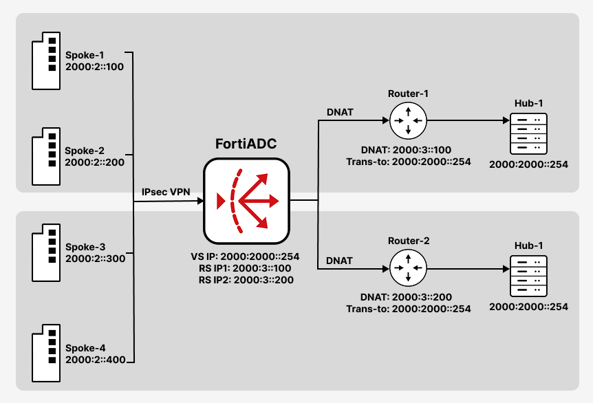
Each Real Server is configured with the unique physical IP address of a backend hub router, while the tunnel interface on each router is set to 2000:2000::254. This completes the two-step DNAT chain: FortiADC translates the shared destination IP to the router’s real IP, and the router re-translates it to the tunnel interface.
-
Spokes send IPsec VPN traffic to
2000:2000::254(UDP port 500). -
FortiADC uses a Layer 4 Virtual Server to DNAT the traffic to backend VPN hub routers.
-
Each hub router performs a second-level translation to its local tunnel interface, allowing proper tunnel termination.
Step 1: Define Real Servers and Create a Pool
Before creating the Virtual Server, you must define the backend VPN hub routers that FortiADC will forward traffic to. Each router is added as a Real Server using its unique physical IP address. These servers are then grouped into a Real Server Pool, which is referenced by the Virtual Server during traffic distribution.
To configure the Real Server:
-
Navigate to Server Load Balance > Real Server Pool, and click the Real Server tab.
-
Click Create New to display the configuration editor. Configure the required settings.
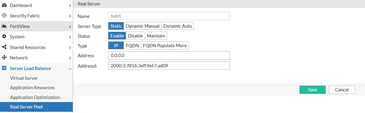
For configuration details, see Configuring real servers. -
Save the configuration.
To configure the Real Server Pool:
-
Navigate to Server Load Balance > Real Server Pool, and click the Real Server Pool tab.
-
Click Create New to configure a new real server pool. Configure the required settings and add the previously configured real server as a member to the real server pool.
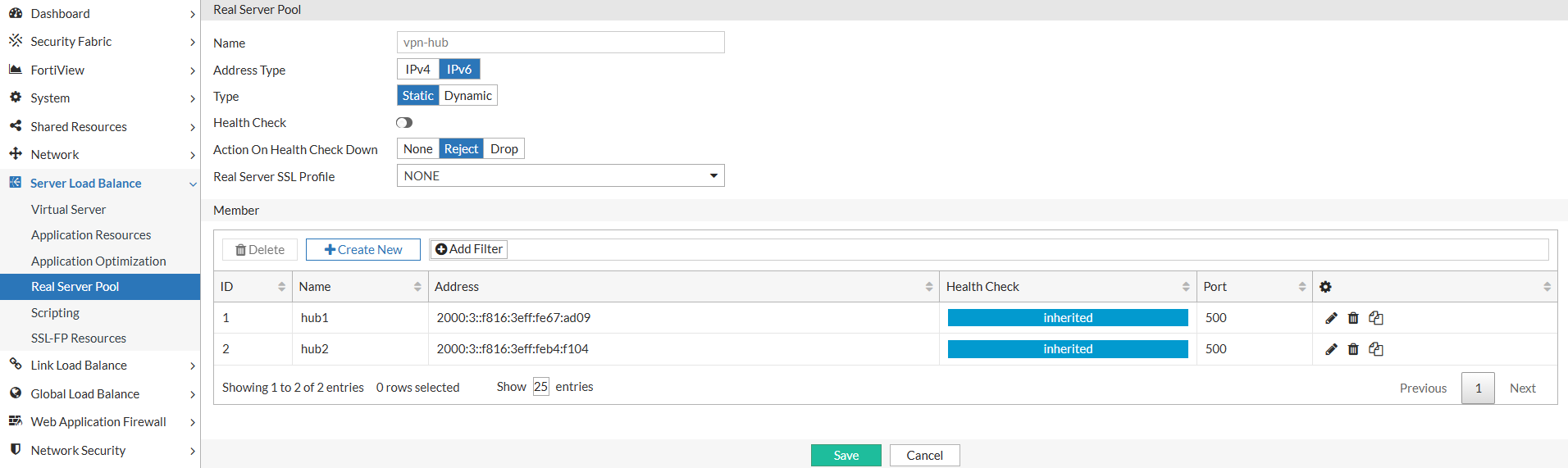
For configuration details, see Using real server pools.
-
Save the configuration.
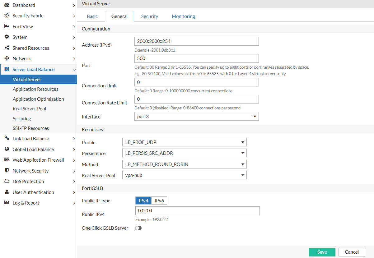
Step 2: Configure the Layer 4 Virtual Server
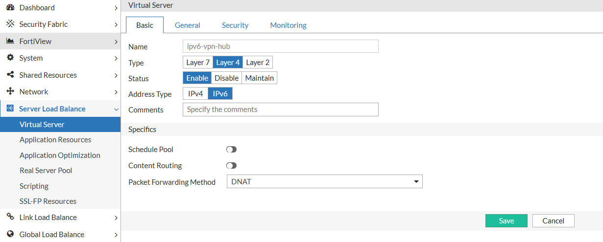
The Virtual Server listens for IPsec VPN traffic on the shared tunnel IP and UDP port 500. It uses Layer 4 packet inspection and DNAT to forward incoming connections to one of the backend hub routers in the configured pool. Persistence is recommended to maintain session consistency for each spoke.
The Virtual Server accepts incoming VPN connections on the shared destination IP and forwards them to a healthy backend router using DNAT.
To configure the Layer 4 Virtual Server:
-
Navigate to Server Load Balance > Virtual Server.
-
In the Virtual Server tab, click Create New > Advanced Mode to display the virtual server configuration editor. Configure the required settings:
-
In the Basic tab:
-
Type: Layer 4
-
Packet Forwarding Method: DNAT
-
-
In the General tab:
-
Address: the hub IP address (e.g.
2000:2000::254) -
Port: 500
-
Profile: LB_PROF_UDP
-
Persistence: LB_PERSIS_SRC_ADDR
-
Real Server Pool: Select the pool configured in Step 1
-
-
-
Save the configuration.
Step 3: Enable Health Checks for Failover
Health checks allow FortiADC to detect when a backend router becomes unavailable. By associating a health check profile with the Real Server Pool, FortiADC can automatically remove unreachable routers from the load-balancing rotation, ensuring that VPN connections are only directed to healthy hubs.
Health checks ensure traffic is only routed to available routers.
To enable Health Check in the Real Server Pool:
-
Navigate to Server Load Balance > Real Server Pool.
-
Click the Edit icon for the appropriate real server pool.
-
Enable Health Check and select LB_HLTHCK_ICMP from the Health Check List.
Ensure backend routers respond to ICMP Echo Requests.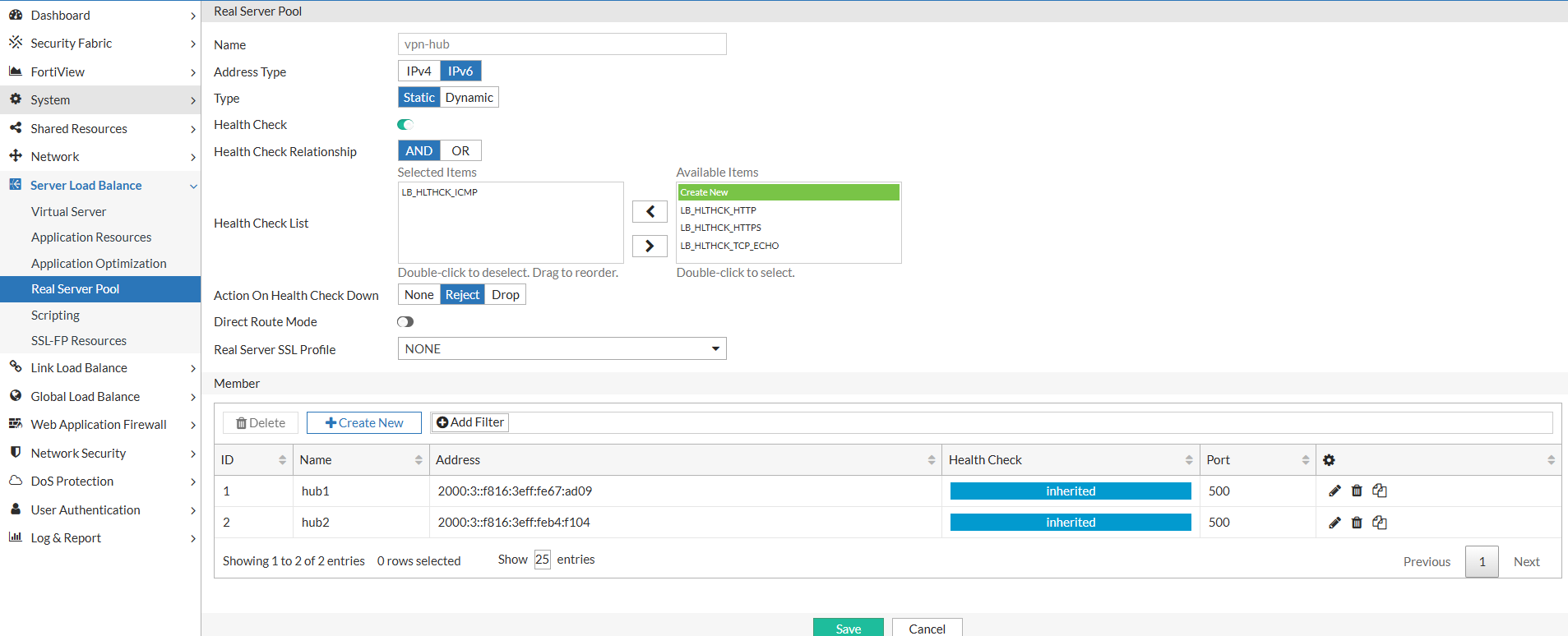
-
Save the configuration.