
Redundant internet connections
In this example, you will create a WAN link interface that provides your FortiGate unit with redundant Internet connections from two Internet service providers (ISPs). The WAN link interface combines these two connections into a single interface.
This example includes weighted load balancing so that most of your Internet traffic is handled by one ISP.

1. Connecting your ISPs to the FortiGate
Connect your ISP devices to your FortiGate so that the ISP you wish to use for most traffic is connected to WAN1 and the other connects to WAN2.

2. Deleting security policies and routes that use WAN1 or WAN2
You will not be able to add an interface to the WAN link interface if it is already used in the FortiGate's configuration, so you must delete any security policies or routes that use either WAN1 or WAN2. Traffic will not be able to reach WAN1 or WAN2 through the FortiGate after you delete the existing policies.
Many FortiGate models include a default Internet access policy that uses WAN1. This policy must also be deleted.
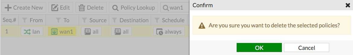
Go to Policy & Objects > IPv4 Policy and delete any policies that use WAN1 or WAN2.
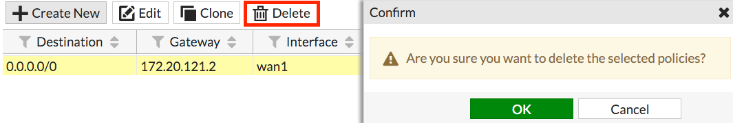
Go to Network > Static Routes and delete any routes that use WAN1 or WAN2.
3. Creating a WAN link interface
Go to Network > WAN LLB (WAN Link Load Balancing).
Set the Interface State to Enable.

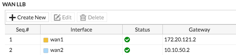
Under WAN LLB, select Create New to add an interface.
Add wan1 and enter the Gateway IP provided by your primary ISP. Do the same for wan2, but this time use the Gateway IP provided by your secondary ISP.
Under Load Balancing Algorithm, select Volume as the type. This will allow you to prioritize the wan1 interface so that more traffic uses it. For the weight, set wan1 to 3 and set wan2 to 1.
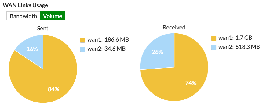
The weight settings will cause 75% of traffic to use WAN1, with the remaining 25% using WAN2.

To help analyze the effectiveness of the algorithm selected, the WAN Links Usage graph shows you the volume and bandwidth usage.
4. Configuring Health Check (optional)
You can optionally configure Health Check to verify the health and status of the links that make up the virtual WAN link. Health Check is only available via the CLI. Go to Dashboard > CLI and enter the following commands:
config system virtual-wan-link
    set fail-detect [enable | disable]
    set fail-alert-interfaces (available only if fail-detect is enabled)
    config health-check
        edit [health check name]
            set server <string>
            set protocol [ping | tcp-echo | udp-echo | http | twamp ]
            ...
            set timeout <integer>
            set failtime [1-10]
            set recoverytime [1-10]
            set update-cascade-interface [enable | disable]
            set update-static-route [enable | disable ]
        next
    end
end
5. Creating a default route for the WAN link interface
Go to Network > Static Routes and create a new default route.
Set Device to the WAN link interface.

6. Allowing traffic from the internal network to the WAN link interface
Go to Policy & Objects > IPv4 and create a new policy.
Set Incoming Interface to your internal network's interface and set Outgoing Interface to the WAN link interface.
Turn on NAT.

Scroll down to view the Logging Options. To view the results later, turn on Log Allowed Traffic and select All Sessions.

7. Results
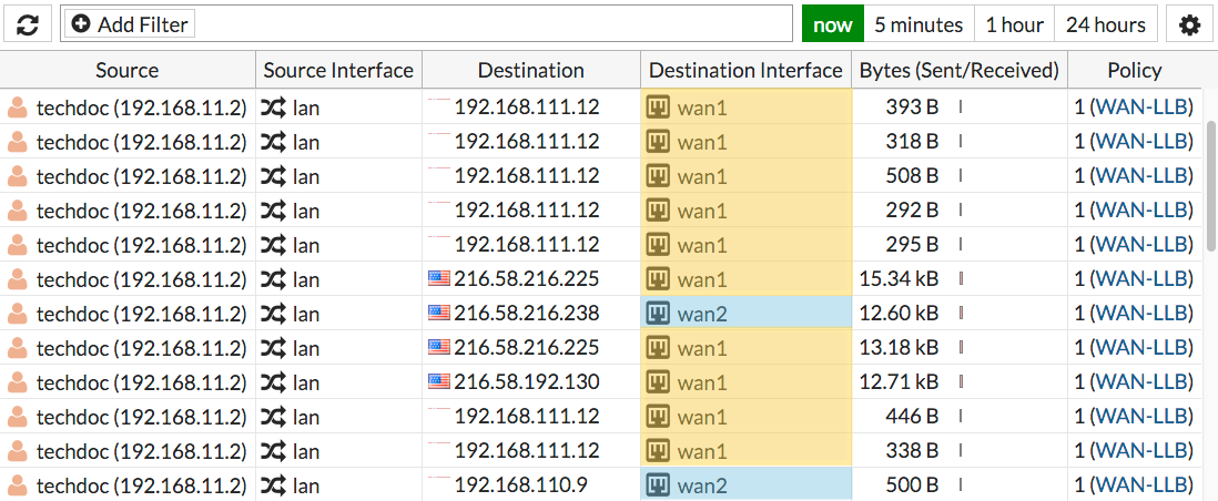
Browse the Internet using a computer on the internal network and then go to FortiView > All Sessions.
Make sure that the Destination Interface column is shown. If it's not, right-click on the top menu row to add it to the menu.
The log shows traffic flowing through both WAN1 and WAN2.
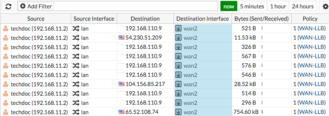
Go to Network > Interfaces and disable the wan1 port. Then browse the Internet from the internal network.

Go back to FortiView > All Sessions and the results should show that traffic is only flowing through wan2, until you enable WAN1 again.
For further reading, check out Redundant Internet installation in the FortiOS 5.4 Handbook.
