


Creating a zero-touch configuration
You can create a zero-touch configuration using switch tags, FortiSwitch serial numbers, or a single FortiSwitch model. Zero-touch configurations are run on a scheduled date and time or when FortiSwitch units are deployed in FortiLAN Cloud. You can apply CLI commands or GUI configuration templates, update the firmware, or both.
To create a zero-touch configuration:
- Go to Configuration > Zero Touch Configurations.
- Select Add.
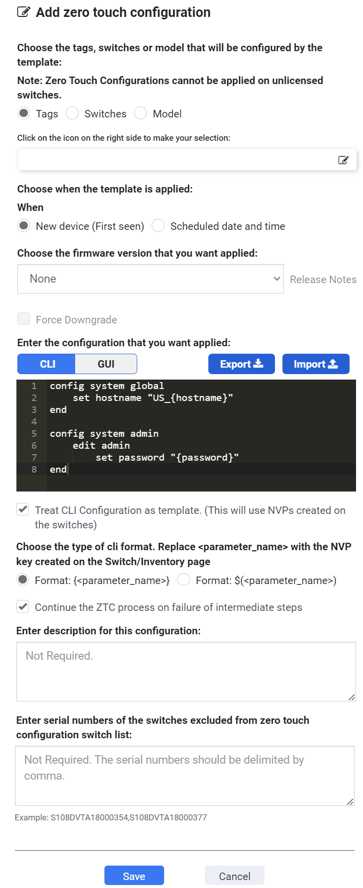
- Select Tags, Switches, or Model.
- If you select Tags, select one or more switch tags to apply the zero-touch configuration to.
- If you select Switches, select one or more FortiSwitch units.
NOTE: Do not include the same switch or switches in both a zero-touch configuration and a scheduled upgrade. - If you select Model, select a FortiSwitch model to apply the zero-touch configuration to.
- Select when the firmware upgrade and configuration are applied.
- If you select New device (First seen), the firmware is upgraded and the configuration applied when FortiSwitch units are deployed in FortiLAN Cloud.
- If you select Scheduled date and time, select the date and time for the firmware to be upgraded and the configuration applied .
- If you want to change the firmware version, select the firmware image to apply.
The available firmware images and the latest version are listed. Click the help link, Release Notes, to learn about the available versions. - Select Force Downgrade to forcefully downgrade newly deployed FortiSwitches.
- Enter the CLI commands to apply to the selected FortiSwitch model or create a CLI template.
A CLI template has parameter names (placeholders) instead of static parameter values. The parameter names are resolved dynamically to their switch specific parameter values when the CLI template is applied to a switch, as defined in the NVP data; the variables ($param) are declared in the NVP and called in the CLI template. See Defining Switch Name-Value Pairs. The parameter values are contained in braces.
Enable Treat CLI Configuration an template to use configured templates. This example sets different values for hostname and password on multiple switches.
Select Continue the ZTC process on failure of intermediate steps to proceed with ZTC, bypassing intermediate failures (if any). If disabled, the ZTC process is halted in the event of an intermediate failure. For example, in case of a firmware failure, the CLI and GUI template configurations are not pushed to the FortiSwitch. This option is enabled by default; disable it if you want to halt the ZTC process in the event of any intermediate failures.
Refer to the FortiSwitchOS CLI Reference for available commands.
NOTE: You can enter 250 KB of CLI commands.
OR
Create a GUI template, click Add and create the following template configurations.- VLAN - Create template configurations to add a VLAN, modify an existing VLAN or delete a VLAN. To configure a template, see VLAN Templates.
- Ports - To configure the administrative status and PoE status of the FortiSwitch, see Ports.
- Interfaces - To configure interface VLANs, see Configuring interface VLANs.
- Port Security - To configure 802.1x/802.1x MAC based security, see Editing the port security.
- Packet Capture - To configure a packet capture profile, see Creating a packet capture profile. You can add a packet capture profile, modify an existing profile or delete a profile.
- Trunk - To configure a trunk, see Creating a trunk . You can add a trunk, modify an existing trunk or delete a trunk.
- IGMP - To configure IGMP settings, update the following parameters. You cannot modify Action.
- LLDP - To configure LLDP Settings, update the following parameters. You cannot modify Action.
- To configure LLDP Profile, update the following parameters. You can add an LLDP profile, modify an existing profile or delete a profile.
- Maximum frame size TLV - This TLV sends the maximum frame size value of the port. If this variable is changed, the sent value will reflect the updated value.
- PoE+ classification TLV - This TLV sends whether there is software PoE negotiation on the port.
- Efficient Energy Ethernet Config - This TLV sends whether energy-efficient Ethernet is enabled on the port. If this variable is changed, the sent value will reflect the updated value.
- Automatic ISL Hello Timer - The time for the automatic inter-switch LAG hello timer. The valid range is 1 - 30 seconds and the default is 3 seconds.
- Automatic ISL timeout - The time before the automatic inter-switch LAG times out if no response is received. The valid range is 0 - 300 seconds and the default is 60 seconds.
- Automatic inter-switch LAG port group - The automatic inter-switch LAG port group identifier. The valid range is 0 - 9.
- Name - Select which MED network policy type-length-value (TLV) category to edit; Voice, Voice Signalling, Guest Voice, Guest Voice Signalling, Softphone Voice, Video Conferencing, Streaming video, Video Signalling.
- Status - Enable or disable whether this TLV is transmitted.
- Assign VLAN - Enable or disable whether to assign a VLAN interface.
- VLAN - The VLAN interface to advertise. The valid range is 0 - 4094.
- Priority - Tthe advertised Layer-2 priority. The valid range is 0 - 7, set to 7 for the highest priority.
- DSCP - The advertised DSCP value to indicate the level of service requested for the traffic. The valid range is 0 - 63.
- Name – Select which MED location type-length-value (TLV) category to edit; Civic Address, Co-ordinates, ELIN Number.
- Status – Enable or disable whether this TLV is transmitted.
- Sys Location ID – If the status is enabled then you can enter the location service identifier. The maximum length is 63 characters.
- Name - The name of a custom TLV entry.
- Oui – The organizationally unique identifier (OUI), a 3-byte hexadecimal number, for this TLV.
- Subtype – The organizationally defined subtype. The valid range is 0 – 255.
- Information String – The organizationally defined information string in hexadecimal bytes.
- ACL - To configure ACL Settings, update the following parameters. You cannot modify Action.
Parameter
Description
Density Mode
Enable the ACL density mode. Trunk Load Balance Enable trunk load balancing. To configure Ingress (for incoming traffic), Egress (for outgoing traffic), and Preelookup (for processing traffic) policies, update the following parameters.
Parameter
Description
ID A unique identifier for this profile. The valid range is 1 - 2048. Active Enable to activate the profile. Group ID A unique group identifier. The valid range is 1 - 2048. Ingress Interface All Enable to apply the profile to all interfaces. Ingress Interface The specific interfaces to apply the profile to. Schedule The schedule for when the ACL profile is enforced. Description
The description for the profile.
Classifier - Identification of packets that the policy is applied to, each packet is classified based on one or more criteria as per these configurations.
VLAN ID to be matched
The VLAN identifier to match.
Cost of Service
The cost of service (CoS) value to match. The valid range is 0 - 7, leave blank to disable this field.
802.1Q CoS value to be matched
The 802.1Q CoS value to match. The valid range is 0 - 7, leave blank to disable this field.
Ethernet type to be matched
The Ethernet type to match. The valid range is 1-65535.
ACL Custom Service to be matched
The pre-configured custom service type to match.
Source MAC
The source MAC address to match.
Destination MAC
The destination MAC address to match.
Source IP Prefix
The source IP address to match (IPv4 only).
Destination IP Prefix
The destination IP address to match IPv4 only).
Action - If a packet matches the classifier criteria for a given ACL, different actions are applied to a packet based on these configurations.
Count
Enable to track the number of matching packets.
Drop
Enable to drop matching packets.
Mirror Session Name
The name of the mirror to use collect packets to analyze.
Redirect Bcast Cpu
Enable to redirect broadcast traffic to all ports including the CPU.
Redirect Bcast No Cpu
Enable to redirect broadcast traffic to all ports excluding the CPU.
Outer VLAN Tag
The outer VLAN tag.
CoS Queue
The CoS queue number. The valid range is 0 - 7, leave blank to disable this field.
Remark CoS
The CoS marking value. The valid range is 0 - 7, leave blank to disable this field.
CPU COS queue number(17 - 25). Only if packets reach to CPU
The CPU CoS queue number. This CoS queue is only used if the packets reach the CPU. The valid range is 17 - 25.
Remark DSCP
The DSCP marking value. The valid range is 0 - 63, leave blank to disable this field.
Redirect Interface
The redirect interface to use.
Redirect Physical Port
The physical ports to include in the egress mask or to redirect packets to.
Egress Mask Interface
The physical ports that are included in the egress mask.
Policer ID
The policer ID to use.
To configure the Policer, update the following parameters. You can add, modify, or delete an existing policer.
Parameter
Description
ID A unique number to identify this policer. The valid range is 1-2048. Type Whether the policer is for the egress policy or the ingress policy. Guaranteed Bandwidth
The amount of bandwidth guaranteed (in Kb/second) to be available for traffic controlled by the policy. The valid range is 1-524287000 Kb.
Guaranteed Burst
The guaranteed burst size in bytes. The valid range is 1-4294967295 bytes.
Maximum Burst
The maximum burst size in bytes. The valid range is 1-4294967295 bytes.
Description
A description of the policer.
To configure the Custom Service, update the following parameters. You can add, modify, or delete an existing policer.
Parameter
Description
Name The name of the ACL custom service. Comment A description of the custom service. Color The icon color for the service in the Service page. Protocol The protocol to use with the custom service, TCP, ICMP, IP, UDP, or SCTP.
- Port Range - [TCP, UDP, or SCTP] The destination ports and source ports. You can enter a single port or a range of ports in each field.
- Protocol Number - [IP] The protocol number.
- ICMP Type/ICMP Code - [ICMP] The ICMP type and code.The valid range is 0 - 254.
Logging - To configure external Syslog server for switch logs, update the following parameters. You cannot modify Action.
Parameter
Description
Event Types The types of log messages sent to the Syslog server. You can enable logging activity messages for the following categories.
- Link
- PoE
- Router
- Spanning Tree
- Switch
- Switch Controller
- System
- User
- FOS Legacy
Syslog Severity Select the least severity level to log from the following options.
- Emergency - The system is unusable.
- Alert - Immediate action is required.
- Critical - Functionality is affected.
- Error - An erroneous condition exists and functionality is probably affected.
- Warning - Functionality might be affected.
- Notification - Information about normal events.
- Information - General information about system operations.
- Debug - Information used for diagnosing or debugging the system.
Syslog Server Update the following Syslog server parameters.
- Server - The IPv4 address or hostname (FQDN) of the remote Syslog server.
- Port - The port number of Syslog server. The valid range is 1-65535 and the default is 514.
- Source IP - The source IPv4 address of the Syslog server.
- CSV - To enable/disable CSV.
Parameter
Description
Aging Time The maximum time to retain a multicast snooping entry for which no packets are visible. The valid range is 15 - 3600 seconds.
Query Interval The maximum time after which the IGMP query is sent. The valid range is 10 - 1200 seconds.
Proxy Report Interval The unsolicited report interval time period. The valid range is 1 - 260 seconds.
Leave Response Timeout The time that the FortiSwitch waits after sending group specific queries in response to the leave message. The valid range is 1 - 20 seconds.
Parameter
Description
Status
Enable/Disable the LLDP transmit and receive feature.
Management Interface The primary management interface advertised in LLDP. Number of TX intervals before local LLDP data expires The number of Tx intervals before local LLDP data expires, that is, the packet TTL (in seconds) is tx-hold times tx-interval. The valid range is 1 - 16.
Frequency of LLDP PDU transmit (seconds) The frequency of LLDP PDU transmission. The valid range is 5 - 4095.
Fast Start The frequency of LLDP PDU transmit for the first 4 packets when the link comes up. Configure the Fast Start Interval, the valid range is 2 - 5 seconds.
Device Detection
Enable/disable dynamic updates of LLDP neighbour devices to FortiLink.
Parameter
Description
Profile Name
A unique name of the Profile. The valid range is 63 characters. Transmitted IEEE 802.1 TLVs.(Port VLAN ID) Enable to transmit the IEEE 802.1 port native-VLAN Type-Length-Value (TLV). Transmitted IEEE 802.3 TLVs. Enable to transmit the IEEE 802.3 organizationally-specific TLVs. The following options are available, you can select more than one.
Auto MCLAG inter chassis link Enable the multi-chassis link aggregation group (MCLAG). Enable/disable automatic Inter-Switch LAG Enable or disable the automatic inter-switch LAG.
Transmitted LLDP-MED TLVs
Select the LLDP-Media Endpoint Discovery (MED) TLVs to transmit; Inventory Managment TLVs, Network Policy TLVs, Power Management TLV, and Location Identification TLVs. You can select one or more option. MED Network Policy
Enter the following for MED network policy.
MED location Service
Enter the following for MED location services.
Custom TLVs
Enter the following for custom TLVs.
Logging - To configure external Syslog server for switch logs, update the following parameters. You cannot modify Action.
- VLAN - Create template configurations to add a VLAN, modify an existing VLAN or delete a VLAN. To configure a template, see VLAN Templates.
- Ports - To configure the administrative status and PoE status of the FortiSwitch, see Ports.
- Interfaces - To configure interface VLANs, see Configuring interface VLANs.
- Port Security - To configure 802.1x/802.1x MAC based security, see Editing the port security.
- Packet Capture - To configure a packet capture profile, see Creating a packet capture profile. You can add a packet capture profile, modify an existing profile or delete a profile.
- Trunk - To configure a trunk, see Creating a trunk . You can add a trunk, modify an existing trunk or delete a trunk.
- IGMP - To configure IGMP settings, update the following parameters. You cannot modify Action.
- System Interfaces - You can configure physical and VLAN interfaces on a FortiSwitch. To configure interfaces, update the following parameters.
Enter the unique virtual router identifier (ID).
Enter the VRRP group number.
Enter the priority. If the highest priority value of 255 is entered, the virtual router becomes the master router.
If the master router fails, the VRRP automatically assigns one of the backup routers without affecting network traffic. When the failed router is functioning again, it becomes the master router again.Select Preempt if you want the router to preempt the master virtual router if the priority changes.
Enter the source virtual IP address that will be shared across the VRRP group.
- LLDP - To configure LLDP Settings, update the following parameters. You cannot modify Action.
- To configure LLDP Profile, update the following parameters. You can add an LLDP profile, modify an existing profile or delete a profile.
- Maximum frame size TLV - This TLV sends the maximum frame size value of the port. If this variable is changed, the sent value will reflect the updated value.
- PoE+ classification TLV - This TLV sends whether there is software PoE negotiation on the port.
- Efficient Energy Ethernet Config - This TLV sends whether energy-efficient Ethernet is enabled on the port. If this variable is changed, the sent value will reflect the updated value.
- Automatic ISL Hello Timer - The time for the automatic inter-switch LAG hello timer. The valid range is 1 - 30 seconds and the default is 3 seconds.
- Automatic ISL timeout - The time before the automatic inter-switch LAG times out if no response is received. The valid range is 0 - 300 seconds and the default is 60 seconds.
- Automatic inter-switch LAG port group - The automatic inter-switch LAG port group identifier. The valid range is 0 - 9.
- Name - Select which MED network policy type-length-value (TLV) category to edit; Voice, Voice Signalling, Guest Voice, Guest Voice Signalling, Softphone Voice, Video Conferencing, Streaming video, Video Signalling.
- Status - Enable or disable whether this TLV is transmitted.
- Assign VLAN - Enable or disable whether to assign a VLAN interface.
- VLAN - The VLAN interface to advertise. The valid range is 0 - 4094.
- Priority - Tthe advertised Layer-2 priority. The valid range is 0 - 7, set to 7 for the highest priority.
- DSCP - The advertised DSCP value to indicate the level of service requested for the traffic. The valid range is 0 - 63.
- Name – Select which MED location type-length-value (TLV) category to edit; Civic Address, Co-ordinates, ELIN Number.
- Status – Enable or disable whether this TLV is transmitted.
- Sys Location ID – If the status is enabled then you can enter the location service identifier. The maximum length is 63 characters.
- Name - The name of a custom TLV entry.
- Oui – The organizationally unique identifier (OUI), a 3-byte hexadecimal number, for this TLV.
- Subtype – The organizationally defined subtype. The valid range is 0 – 255.
- Information String – The organizationally defined information string in hexadecimal bytes.
- ACL - To configure ACL Settings, update the following parameters. You cannot modify Action.
Parameter
Description
Density Mode
Enable the ACL density mode. Trunk Load Balance Enable trunk load balancing. To configure Ingress (for incoming traffic), Egress (for outgoing traffic), and Preelookup (for processing traffic) policies, update the following parameters.
Parameter
Description
ID A unique identifier for this profile. The valid range is 1 - 2048. Active Enable to activate the profile. Group ID A unique group identifier. The valid range is 1 - 2048. Ingress Interface All Enable to apply the profile to all interfaces. Ingress Interface The specific interfaces to apply the profile to. Schedule The schedule for when the ACL profile is enforced. Description
The description for the profile.
Classifier - Identification of packets that the policy is applied to, each packet is classified based on one or more criteria as per these configurations.
VLAN ID to be matched
The VLAN identifier to match.
Cost of Service
The cost of service (CoS) value to match. The valid range is 0 - 7, leave blank to disable this field.
802.1Q CoS value to be matched
The 802.1Q CoS value to match. The valid range is 0 - 7, leave blank to disable this field.
Ethernet type to be matched
The Ethernet type to match. The valid range is 1-65535.
ACL Custom Service to be matched
The pre-configured custom service type to match.
Source MAC
The source MAC address to match.
Destination MAC
The destination MAC address to match.
Source IP Prefix
The source IP address to match (IPv4 only).
Destination IP Prefix
The destination IP address to match IPv4 only).
Action - If a packet matches the classifier criteria for a given ACL, different actions are applied to a packet based on these configurations.
Count
Enable to track the number of matching packets.
Drop
Enable to drop matching packets.
Mirror Session Name
The name of the mirror to use collect packets to analyze.
Redirect Bcast Cpu
Enable to redirect broadcast traffic to all ports including the CPU.
Redirect Bcast No Cpu
Enable to redirect broadcast traffic to all ports excluding the CPU.
Outer VLAN Tag
The outer VLAN tag.
CoS Queue
The CoS queue number. The valid range is 0 - 7, leave blank to disable this field.
Remark CoS
The CoS marking value. The valid range is 0 - 7, leave blank to disable this field.
CPU COS queue number(17 - 25). Only if packets reach to CPU
The CPU CoS queue number. This CoS queue is only used if the packets reach the CPU. The valid range is 17 - 25.
Remark DSCP
The DSCP marking value. The valid range is 0 - 63, leave blank to disable this field.
Redirect Interface
The redirect interface to use.
Redirect Physical Port
The physical ports to include in the egress mask or to redirect packets to.
Egress Mask Interface
The physical ports that are included in the egress mask.
Policer ID
The policer ID to use.
To configure the Policer, update the following parameters. You can add, modify, or delete an existing policer.
Parameter
Description
ID A unique number to identify this policer. The valid range is 1-2048. Type Whether the policer is for the egress policy or the ingress policy. Guaranteed Bandwidth
The amount of bandwidth guaranteed (in Kb/second) to be available for traffic controlled by the policy. The valid range is 1-524287000 Kb.
Guaranteed Burst
The guaranteed burst size in bytes. The valid range is 1-4294967295 bytes.
Maximum Burst
The maximum burst size in bytes. The valid range is 1-4294967295 bytes.
Description
A description of the policer.
To configure the Custom Service, update the following parameters. You can add, modify, or delete an existing policer.
Parameter
Description
Name The name of the ACL custom service. Comment A description of the custom service. Color The icon color for the service in the Service page. Protocol The protocol to use with the custom service, TCP, ICMP, IP, UDP, or SCTP.
- Port Range - [TCP, UDP, or SCTP] The destination ports and source ports. You can enter a single port or a range of ports in each field.
- Protocol Number - [IP] The protocol number.
- ICMP Type/ICMP Code - [ICMP] The ICMP type and code.The valid range is 0 - 254.
Router - Routing configuration is supported on FortiSwitches managed by FortiLAN Cloud. You can add/modify the following configurations. Routing information and interfaces are monitored on the Routing Table and Link Monitor pages.
Parameter
Description
Static and IPv6 Static To provide remote access to the management port, configure an IPv4 or IPv6 static route. Set the gateway address to the IPv4 or IPv6 address of the router.
Configure the following for IPv4 static route.
- The Destination IP/ Netmask for the route.
- Enable Blackhole to disable all the Gateway options.
- The pre-configured Gateway out interface.
- Enable Dynamic Gateway to disable the Gateway option.
- The Gateway router IPv4 address.
Configure the following for IPv6 static route.
- The Destination IP/ Netmask for the route.
- Enable Blackhole to disable all the Gateway options.
- The pre-configured Gateway out interface.
- The Gateway router IPv6 address.
- The administrative Distance for all routes.
- Enable the BFD (Bidirectional Forwarding Detection).
Link Probes You can create a probe to monitor the link to a server. The FortiLAN Cloud sends periodic ping messages to test that the server is available.
- The Source Interface. Can be the physical or VLAN interface name.
- The Protocol to detect the server. Select ARP or ping.
- The Source IP address used in packet to the server.
- The Gateway IP address used to ping the server.
You can configure the following Advanced Settings.
- Detection Interval (Seconds) - The detection interval in seconds. The range is 1-3600.
- Detection Timeout (Seconds) - The detection request timeout in seconds. The range is 1-255.
- Retries Before Down - The number of retry attempts before bringing the server down.
- Retries Before Up - The number of retry attempts before bringing the server up.
OSPF Open shortest path first (OSPF) is a link-state interior routing protocol that is widely used in large enterprise organizations. OSPF provides routing within a single autonomous system (AS).
- Enter the Router IP address.
- Enable Default Information Originate to generate and advertise a default route into the device’s RIP-enabled networks. The generated route may be based on routes learned through a dynamic routing protocol, routes in the routing table, or both.
- Enter the Default Information Metric for routing.
- If you want to Redistribute non-RIP routes, select Enable under Connected, Static, OSPF, BGP, or ISIS. If you select Enable, enter the routing metric to use.
- An OSPF implementation consists of one or more Areas. An area consists of a group of contiguous networks. The FortiSwitch unit supports different types of areas—stub areas, Not So Stubby areas (NSSA), and Regular areas. A stub area is an interface without a default route configured. NSSA is a type of stub area that can import AS external routes and send them to the backbone but cannot receive AS external routes from the backbone or other areas. All other areas are considered regular areas.
- Enter a unique value to identify this Network configuration. Enter an IP address and netmask for your RIP network. You can configure multiple networks.
- Configure ODPF Interface. In the Hello Interval field, enter the number of seconds that the FortiSwitch unit waits between sending hello messages to neighboring PIM routers. If you want to use Authentication, select Text, MD5, or None.
- Enable Bidirectional Forwarding Detection
- Configure the interface Maximum Transmission Unit (MTU) packet size.
- Enable Fast Hello, which provides a way to send multiple hello packets per second.
- Configure the Hello Interval. OSPF Hello protocol is used to discover and maintain communications with neighboring routers. Hello packets are sent out at a regular interval.
The Dead interval is the time other routers wait before declaring a neighbor dead (offline).
RIP
The Routing Information Protocol (RIP) is a distance-vector routing protocol that works best in small networks that have no more than 15 hops. Each router maintains a routing table by sending out its routing updates and by asking neighbors for their routes.
- The FortiSwitch unit supports RIP version 1 and RIP version 2.
- RIP version 1 uses classful addressing and broadcasting to send out updates to router neighbors. It does not support different sized subnets or classless inter-domain routing (CIDR) addressing.
- RIP version 2 supports classless routing and subnets of various sizes. Router authentication supports MD5 and authentication keys. Version 2 uses multicasting to reduce network traffic.
- Enable Default Information Originate to generate and advertise a default route into the device’s RIP-enabled networks. The generated route may be based on routes learned through a dynamic routing protocol, routes in the routing table, or both.
- Enable Bidirectional Forwarding Detection to quickly locate hardware failures in the network. Routers running BFD communicate with each other, and, if a timer runs out on a connection, that router is declared to be down. BFD then communicates this information to RIP, and the routing information is updated.
- Enter the Default Metric. RIP uses hop count as the metric for choosing the best route. A hop count of 1 represents a network that is connected directly to the FortiSwitch unit. A hop count of 16 represents a network that cannot be reached.
- If you want to change the default Timers value, enter the number of seconds in the Update, Timeout, and Garbage fields.
- The update timer determines the interval between routing updates. The default setting is 30 seconds.
- The timeout timer is the maximum time that a route is considered reachable while no updates are received for the route. The default setting is 180 seconds. The timeout timer setting should be at least three times longer than the update timer setting.
- The garbage timer is the is the how long that the FortiSwitch unit advertises a route as being unreachable before deleting the route from the routing table. The default setting is 120 seconds.
- If you want to Redistribute non-RIP routes, select Enable under Connected, Static, OSPF, BGP, or ISIS. If you select Enable, enter the routing metric to use.
- Configure the router Distance. Enter the distance identifier in the ID field and select the Access List. Enter the IP address and netmask.
- Enter a unique value to identify this Network configuration. Enter an IP address and netmask for your RIP network. You can configure multiple networks.
- Configure RIP for the appropriate Interface. If you want to change the RIP version used to send and receive routing updates, select from the Send Version and Receive Version drop-down menus. If you do not want to send RIP updates from this interface, select Passive Interface. If you want to use Authentication, select Text or None.
Multicast
A FortiSwitch unit can operate as a Protocol Independent Multicast (PIM) version-2 router. Add a multicast enabled interface.
- Enter the Multicast Flow value.
- In the Hello Interval field, enter the number of seconds that the FortiSwitch unit waits between sending hello messages to neighboring PIM routers.
- In the Designated Router Priority field, enter a priority to the FortiSwitch unit Designated Router (DR) candidacy. The value is compared to that of other DR interfaces connected to the same network segment, and the router having the highest DR priority is selected to be the DR. If two DR priority values are the same, the interface having the highest IP address is selected.
- In the IGMP Response Time field, enter the number of seconds between queries to IGMP hosts.
- In the IGMP Interval field, enter the maximum number of seconds to wait for an IGMP query response.
Multicast Flows
You can specify a range of multicast group addresses when configuring a multicast flow.
- Enter the Name of the multicast flow.
- In the ID field, enter a number between 1 and 4294967295 to identify the multicast flow entry.
- In the Group Address field, enter the multicast group IPv4 address.
- In the Source Address field, enter an IPv4 address for the multicast source.
Parameter
Description
Aging Time The maximum time to retain a multicast snooping entry for which no packets are visible. The valid range is 15 - 3600 seconds.
Query Interval The maximum time after which the IGMP query is sent. The valid range is 10 - 1200 seconds.
Proxy Report Interval The unsolicited report interval time period. The valid range is 1 - 260 seconds.
Leave Response Timeout The time that the FortiSwitch waits after sending group specific queries in response to the leave message. The valid range is 1 - 20 seconds.
Parameter
Description
Interface Name
Enter the name of the interface. Interface names can't be changed. Alias
Enter an alternate name for a interface on the FortiSwitch unit.
VLAN ID
Enter the VLAN identifier for a VLAN interface.
IP Configuration Static - Configure a static IP address and netmask of the interface.
DHCP - Configure the interface to receive its IP address from an external DHCP server.
Administration Indicates if the interface can be accessed for administrative purposes. If the administrative status is Up, an administrator can connect to the interface using the configured access. If the administrative status is Down, the interface is administratively down and can't be accessed for administrative purposes.
Select the types of access permitted on this interface or secondary IP address.
Secondary IP Add additional IP addresses to this interface. Select the expand arrow to expand or hide the section. DHCP Relay Enable/Disable DHCP relay for the physical interface. VRRP
The Virtual Router Redundancy Protocol (VRRP) uses virtual routers to control which physical routers are assigned to an access network. A VRRP group consists of a master router and one or more backup routers that share a virtual IP address. The VRRP master router sends VRRP advertisement messages to the backup routers. When the VRRP master router fails to send advertisement messages, the backup router with the highest priority takes over as the master router.
To create a VRRP group, you need to create a VRRP virtual MAC address, which is a shared MAC address adopted by the VRRP master.
Parameter
Description
Status
Enable/Disable the LLDP transmit and receive feature.
Management Interface The primary management interface advertised in LLDP. Number of TX intervals before local LLDP data expires The number of Tx intervals before local LLDP data expires, that is, the packet TTL (in seconds) is tx-hold times tx-interval. The valid range is 1 - 16.
Frequency of LLDP PDU transmit (seconds) The frequency of LLDP PDU transmission. The valid range is 5 - 4095.
Fast Start The frequency of LLDP PDU transmit for the first 4 packets when the link comes up. Configure the Fast Start Interval, the valid range is 2 - 5 seconds.
Device Detection
Enable/disable dynamic updates of LLDP neighbour devices to FortiLink.
Parameter
Description
Profile Name
A unique name of the Profile. The valid range is 63 characters. Transmitted IEEE 802.1 TLVs.(Port VLAN ID) Enable to transmit the IEEE 802.1 port native-VLAN Type-Length-Value (TLV). Transmitted IEEE 802.3 TLVs. Enable to transmit the IEEE 802.3 organizationally-specific TLVs. The following options are available, you can select more than one.
Auto MCLAG inter chassis link Enable the multi-chassis link aggregation group (MCLAG). Enable/disable automatic Inter-Switch LAG Enable or disable the automatic inter-switch LAG.
Transmitted LLDP-MED TLVs
Select the LLDP-Media Endpoint Discovery (MED) TLVs to transmit; Inventory Managment TLVs, Network Policy TLVs, Power Management TLV, and Location Identification TLVs. You can select one or more option. MED Network Policy
Enter the following for MED network policy.
MED location Service
Enter the following for MED location services.
Custom TLVs
Enter the following for custom TLVs.

- Additionally, you can export (save) the GUI and CLI configurations, edit and then import them to the GUI to facilitate reuse. Click on Export and Import as required; JSON file format is supported for both operations.
- Enter a description of the zero-touch configuration.
- If you want to exclude one of more FortiSwitch unit of the selected model, enter the serial numbers, separated by a comma.
- Select Save.
The zero-touch configuration is listed on the Zero-Touch Configurations pane.