
FortiGate 400G and 401G fast path architecture
The FortiGate 400G and 401G each include one NP7 processor and one CP10 processor. All front panel data interfaces and the NP7 processor connect to the integrated switch fabric (ISF). All data traffic passes from the data interfaces through the ISF to the NP7 processor. All supported traffic passing between any two data interfaces can be offloaded by the NP7 processor. Data traffic processed by the CPU takes a dedicated data path through the ISF and the NP7 processor to the CPU.
The FortiGate 400G and 401G models feature the following front panel interfaces:
- One 10/100/1000/2.5GBASE-T RJ45 (HA , not connected to the NP7 processor).
- One 10/100/1000BASE-T RJ45 (MGMT, not connected to the NP7 processor).
- Eight 5G/2.5G/1G/100M BASE-T RJ45 (WAN1, WAN2, LAN1 to LAN6).
- Sixteen 1 GigE SFP (LAN7 to LAN22).
- Four 10/1 GigE SFP+/SFP (X1 to X4) (X1 and X2 are FortiLink interfaces).
- Four 25/10 GigE SFP28/SFP+ (X5 to X8).
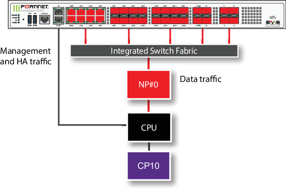
The MGMT interface is not connected to the NP7 processor. Management traffic passes to the CPU over a dedicated management path that is separate from the data path. You can also dedicate separate CPU resources for management traffic to further isolate management processing from data processing (see Improving GUI and CLI responsiveness (dedicated management CPU)).
The HA interface is also not connected to the NP7 processor. To help provide better HA stability and resiliency, HA traffic uses a dedicated physical control path that provides HA control traffic separation from data traffic processing.
The separation of management and HA traffic from data traffic keeps management and HA traffic from affecting the stability and performance of data traffic processing.
You can use the following command to display the FortiGate 400G or 401G NP7 configuration.
diagnose npu np7 port-list
Front Panel Port:
Name     Max_speed(Mbps) Dflt_speed(Mbps) Sw_Trunk_Id     Sw_Tcam_Id GroupID AsVdom  Switch_id SW_port_id SW_port_name
-------- --------------- ---------------  --------------- ---------- ------- ------- --------- ---------- ------------
wan1     5000            5000             8               1          0       0       0         19         n/a
wan2     5000            5000             8               2          0       0       0         18         n/a
lan1     5000            5000             8               3          0       0       0         21         n/a
lan2     5000            5000             8               4          0       0       0         20         n/a
lan3     5000            5000             8               5          0       0       0         23         n/a
lan4     5000            5000             8               6          0       0       0         22         n/a
lan5     5000            5000             8               7          0       0       0         25         n/a
lan6     5000            5000             8               8          0       0       0         24         n/a
lan7     1000            1000             8               9          0       0       0         3          n/a
lan8     1000            1000             8               10         0       0       0         5          n/a
lan9     1000            1000             8               11         0       0       0         4          n/a
lan10    1000            1000             8               12         0       0       0         2          n/a
lan11    1000            1000             8               13         0       0       0         9          n/a
lan12    1000            1000             8               14         0       0       0         8          n/a
lan13    1000            1000             8               15         0       0       0         7          n/a
lan14    1000            1000             8               16         0       0       0         6          n/a
lan15    1000            1000             8               17         0       0       0         11         n/a
lan16    1000            1000             8               18         0       0       0         13         n/a
lan17    1000            1000             8               19         0       0       0         12         n/a
lan18    1000            1000             8               20         0       0       0         10         n/a
lan19    1000            1000             8               21         0       0       0         17         n/a
lan20    1000            1000             8               22         0       0       0         16         n/a
lan21    1000            1000             8               23         0       0       0         15         n/a
lan22    1000            1000             8               24         0       0       0         14         n/a
x1       10000           10000            8               25         0       0       0         38         n/a
x2       10000           10000            8               26         0       0       0         39         n/a
x3       10000           10000            8               27         0       0       0         40         n/a
x4       10000           10000            8               28         0       0       0         41         n/a
x5       25000           10000            8               29         0       0       0         34         n/a
x6       25000           10000            8               30         0       0       0         35         n/a
x7       25000           10000            8               31         0       0       0         36         n/a
x8       25000           10000            8               32         0       0       0         37         n/a
-------- --------------- ---------------  --------------- ---------- ------- ------- --------- ---------- ------------

Name     sw_id hash nr_link valid default sw_tid
-------- ---------------------------------------
-------- ---------------------------------------

NP Port:
Name   Switch_id SW_port_id SW_port_name
------ --------- ---------- ------------
np0_0  0         30         n/a
np0_1  0         26         n/a
------ --------- ---------- ------------
* Max_speed: Maximum speed, Dflt_speed: Default speed
* SW_port_id: Switch port ID, SW_port_name: Switch port name
The command output also shows the maximum speed, default speed, and NP group for each interface.
The NP7 processor has a bandwidth capacity of 200 Gigabits. You can see from the command output that if all interfaces were operating at their maximum bandwidth the NP7 processor would not be able to offload all the traffic.
Configuring FortiGate 400G and 401G NPU port mapping
You can use the following command to configure FortiGate-400G and 401G NPU port mapping:
config system npu-post
config port-npu-map
edit <interface-name>
set npu-group {All-NP | NP0-link0 | NP0-link1}
end
end
end
You can use port mapping to assign data interfaces or LAGs to send traffic to selected NP7 processor links.
<interface-name> can be a physical interface or a LAG.
All-NP, (the default) distribute sessions to the LAG connected to NP0.
NP0-link0, send sessions to NP0 link 0.
NP0-link1, send sessions to NP0 link 1.
NP0-link0 NP0-link1, send sessions to both NP0 link 0 and NP0 link 1.
For example, use the following syntax to assign the FortiGate-400G front panel X5 interface to NP0-link0 and X6 interface to NP0-link 1. The resulting configuration splits traffic from the X5 and X6 interfaces between the two NP7 links:
config system npu-post
config port-npu-map
edit x5
set npu-group NP0-link0
next
edit x6
set npu-group NP0-link1
end
end
While the FortiGate-400G or 401G is processing traffic, you can use the diagnose npu np7 cgmac-stats <npu-id> command to show how traffic is distributed to the NP7 links.
You can use the diagnose npu np7 port-list command to see the current NPU port map configuration. For example, after making the changes described in the example, the output of the diagnose npu np7 port-list command shows different Sw_Trunk_Ids for X5 and X6 and these interfaces are listed in a port mapping summary at the bottom of the command output.