
FortiGate 4800F and 4801F fast path architecture
The FortiGate 4800F and 4801F each include sixteen NP7 processors. All front panel data interfaces and the NP7 processors connect to the integrated switch fabric (ISF). All supported traffic passing between any two data interfaces can be offloaded by the NP7 processors. Because of the ISF, all data traffic passes from the data interfaces through the ISF to the NP7 processors. Data traffic processed by the CPU takes a dedicated data path through the ISF and an NP7 processor to the CPU.
The FortiGate 4800F and 4801F models feature the following front panel interfaces:
- Two 10/100/1000BASE-T RJ45 (MGMT1 and MGMT2, not connected to the NP7 processor).
- Twelve 50/25/10/1 GigE SFP56 (HA1, HA2 , AUX1, AUX2, 1 to 8) HA1, HA2 , AUX1, AUX2 not connected to the NP7 processors.
- Twelve 200/100/40 GigE QSFP56 (9 to 20). Each of these interfaces can be split into four 50 GigE SFP28/SFP56 interfaces.
- Eight 400/200/100/40 GigE QSFP-DD (21 to 28). Each of these interfaces can be split into eight 50GigE interfaces, four 100GigE interfaces, or two 200 GigE interfaces.
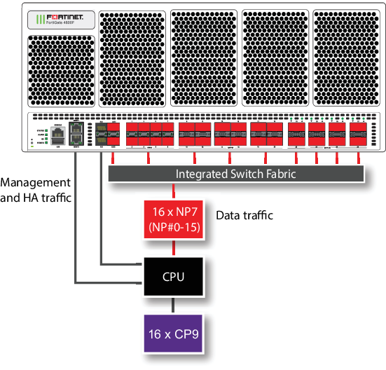
The MGMT interfaces are not connected to the NP7 processors. Management traffic passes to the CPU over a dedicated management path that is separate from the data path. You can also dedicate separate CPU resources for management traffic to further isolate management processing from data processing (see Improving GUI and CLI responsiveness (dedicated management CPU)).
The HA interfaces are also not connected to the NP7 processors. To help provide better HA stability and resiliency, HA traffic uses a dedicated physical control path that provides HA control traffic separation from data traffic processing.
The separation of management and HA traffic from data traffic keeps management and HA traffic from affecting the stability and performance of data traffic processing.
The AUX interfaces are connected to the NP7 processors and function similar to data interfaces. You can use the AUX interfaces for FGSP or FGCP HA session synchronization. If you license the FortiGate 4800F or 4801F for hyperscale firewall, you can use the AUX interfaces for hardware logging or FGGP or FGSP HA hardware session synchronization.
|
|
You can use the |
You can use the following command to display the FortiGate 4800F and 4801F NP7 configuration. The command output shows that all sixteen NP7s are connected to all front panel data interfaces and to the AUX 1 and AUX2 interfaces.
diagnose npu np7 port-list
Front Panel Port:
Name     Max_speed(Mbps) Dflt_speed(Mbps) Sw_Trunk_Id     Sw_Tcam_Id Group_from_vdom Switch_id SW_port_id SW_port_name
-------- --------------- ---------------  --------------- ---------- --------------- --------- ---------- ------------
port1    50000           10000            8               1          1               0         167        n/a
port2    50000           10000            8               2          1               0         168        n/a
port3    50000           10000            8               3          1               0         169        n/a
port4    50000           10000            8               4          1               0         170        n/a
port5    50000           10000            8               5          1               0         172        n/a
port6    50000           10000            8               6          1               0         173        n/a
port7    50000           10000            8               7          1               0         174        n/a
port8    50000           10000            8               8          1               0         175        n/a
port9    200000          100000           8               9          1               0         179        n/a
port10   200000          100000           8               10         1               0         183        n/a
port11   200000          100000           8               11         1               0         191        n/a
port12   200000          100000           8               12         1               0         187        n/a
port13   200000          100000           8               13         1               0         195        n/a
port14   200000          100000           8               14         1               0         199        n/a
port15   200000          100000           8               15         1               0         207        n/a
port16   200000          100000           8               16         1               0         203        n/a
port17   200000          100000           8               17         1               0         211        n/a
port18   200000          100000           8               18         1               0         215        n/a
port19   200000          100000           8               19         1               0         223        n/a
port20   200000          100000           8               20         1               0         219        n/a
port21   400000          400000           8               21         1               0         227        n/a
port22   400000          400000           8               22         1               0         235        n/a
port23   400000          400000           8               23         1               0         243        n/a
port24   400000          400000           8               24         1               0         251        n/a
port25   400000          400000           8               25         1               0         0          n/a
port26   400000          400000           8               26         1               0         8          n/a
port27   400000          400000           8               27         1               0         16         n/a
port28   400000          400000           8               28         1               0         24         n/a
aux1     50000           10000            8               31         1               0         165        n/a
aux2     50000           10000            8               32         1               0         166        n/a
-------- --------------- ---------------  --------------- ---------- --------------- --------- ---------- ------------

Name     sw_id hash nr_link valid default sw_tid
-------- ---------------------------------------
-------- ---------------------------------------

NP Port:
Name   Switch_id SW_port_id SW_port_name
------ --------- ---------- ------------
np0_0  0         95         n/a
np0_1  0         91         n/a
np1_0  0         83         n/a
np1_1  0         87         n/a
np2_0  0         56         n/a
np2_1  0         60         n/a
np3_0  0         52         n/a
np3_1  0         48         n/a
np4_0  0         79         n/a
np4_1  0         75         n/a
np5_0  0         67         n/a
np5_1  0         71         n/a
np6_0  0         40         n/a
np6_1  0         44         n/a
np7_0  0         36         n/a
np7_1  0         32         n/a
np8_0  0         159        n/a
np8_1  0         155        n/a
np9_0  0         147        n/a
np9_1  0         151        n/a
np10_0 0         127        n/a
np10_1 0         123        n/a
np11_0 0         115        n/a
np11_1 0         119        n/a
np12_0 0         143        n/a
np12_1 0         139        n/a
np13_0 0         131        n/a
np13_1 0         135        n/a
np14_0 0         111        n/a
np14_1 0         107        n/a
np15_0 0         99         n/a
np15_1 0         103        n/a
------ --------- ---------- ------------
* Max_speed: Maximum speed, Dflt_speed: Default speed
* SW_port_id: Switch port ID, SW_port_name: Switch port name
The command output also shows the maximum and default speeds of each interface.
The integrated switch fabric distributes sessions from the data interfaces to the NP7 processors. The sixteen NP7 processors have a bandwidth capacity of 200Gigabit x 16 = 3200Gigabit. If all data interfaces were operating at their maximum bandwidth, the NP7 processors would not be able to offload all the traffic. You can use NPU port mapping to control how sessions are distributed to NP7 processors.
You can add LAGs to improve performance. For details, see Increasing NP7 offloading capacity using link aggregation groups (LAGs).
For information about hyperscale firewall support, see the Hyperscale Firewall Guide.
Assigning an NP7 processor group to a hyperscale firewall VDOM
If a FortiGate has more than one NP7 processor, to support a hyperscale firewall VDOM, the NP7 processors need to be connected together using RLT channels. Due to the number of channels in an NP7 processor, a maximum of six NP7 processors can be connected together to support a hyperscale firewall VDOM. Any FortiGate with more than six NP7 processors has to be configured to limit the number of NP7 processors that a hyperscale firewall VDOM can send sessions to. FortiGate models with six or fewer NP7 processors can support hyperscale firewall VDOMs without dividing the NP7 processors into different groups.
|
|
Because of the NP7 processor groups feature, if you have applied a hyperscale firewall license to a FortiGate 4800F or 4801F you should not configure NPU port mapping. Instead you should use the |
Since the FortiGate 4800F and 4801F each have sixteen NP7 processors, these models include a new configuration option to assign a group of NP7 processors to to each hyperscale firewall VDOM. In the current implementation, the FortiGate 4800F or 4801F supports assigning a group of four NP7 processors to a hyperscale firewall VDOM. Fortinet could have created different group sizes, but choose four groups of four to make it easier to evenly distribute the processing load among all sixteen of the NP7 processors.
After creating a hyperscale firewall VDOM on the FortiGate 4800F or 4801F, the first thing you should do is use the following options to enable hyperscale firewall features by setting the policy-offload-level to full-offload and to assign an NPU processor group (also called an NP group or an NPU group) to the newly created hyperscale firewall VDOM. You must set the NP7 processor group for the hyperscale firewall VDOM before adding any interfaces to the VDOM. The CLI will not accept the command to assign an NP7 processor group if interfaces have already been added to the hyperscale firewall VDOM.
config system settings
set policy-offload-level full-offload
set npu-group-id {0 | 1 | 2 | 3}
end
0 assign this hyperscale firewall VDOM to NP7 processor group NP#0-3, which includes NP#0, NP#1, NP#2, and NP#3.
1 assign this hyperscale firewall VDOM to NP7 processor group NP#4-7, which includes NP#4, NP#5, NP#6, and NP#7.
2 assign this hyperscale firewall VDOM to NP7 processor group NP#8-11, which includes NP#8, NP#9, NP#10, and NP#11.
3 assign this hyperscale firewall VDOM to NP7 processor group NP#12-15, which includes NP#12, NP#13, NP#14, and NP#15.
You can only assign one NP7 processor group to a hyperscale firewall VDOM.
You can assign the same NP7 processor group to multiple hyperscale firewall VDOMs.
You can now add interfaces to the hyperscale firewall VDOM and continue with creating hyperscale firewall policies and so on.
When you add an interface to a hyperscale firewall VDOM, that interface is assigned to the same NP7 processor group as the VDOM. You can use the diagnose npu np7 port-list command to see the NP7 processor group (check the NP_group column) assigned to each interface.
A VLAN is assigned to the same NP7 processor group as the physical interface that the VLAN is added to. You can move a VLAN to a different hyperscale firewall VDOM than the physical interface, as long as the VDOM is assigned to the same NP7 group as the hyperscale firewall VDOM containing the physical interface.
All of the members of a LAG must be assigned to the same NP7 group.
NP7 processor groups do not affect NP7 offloading of sessions in non-hyperscale firewall VDOMs (such as the root VDOM).
|
|
As an alternative to using the the
To use these NPU port mapping options, instead of assigning a VDOM to an This configuration is not recommended because it would usually be more complex than using the |
NP7 processor groups and hyperscale hardware logging
On a FortiGate 4800F or 4801F, hyperscale hardware logging can only send logs to interfaces in the same NP7 processor group as the NP7 processors that are handling the hyperscale sessions.
This means that, on a FortiGate 4800F or 4801F, hyperscale hardware logging servers must include a hyperscale firewall VDOM. This VDOM must be assigned the same NP7 processor group as the hyperscale firewall VDOM that is processing the hyperscale traffic being logged. This can be the same hyperscale VDOM or another hyperscale firewall VDOM that is assigned the same NP7 processor group.
For more information about hyperscale firewall hardware logging, see Configuring hardware logging.
The following example hyperscale hardware logging configuration could be created for the hyperscale VDOM named Test-hw12. The configuration is a syslog configuration that includes three logging servers each assigned to the Test-hw12 hyperscale firewall VDOM.
config log npu-server
set log-processor host
set syslog-facility 0
set syslog-severity 7
config server-info
edit 1
set vdom Test-hw12
set ipv4-server 10.10.10.72
set source-port 2002
set dest-port 514
next
edit 2
set vdom Test-hw12
set ipv4-server 10.10.10.73
set source-port 2003
set dest-port 514
next
edit 3
set vdom Test-hw12
set ipv4-server 10.10.10.74
set source-port 2004
set dest-port 514
end
config server-group
edit HyperScale_Syslog
set log-format syslog
set server-number 13
set server-start-id 1
end
end
Splitting the port9 to port20 interfaces
You can use the following command to split each FortiGate 4800F or 4801F 9 to 20 (port9 to port20) QSFP56 interface into four 50 GigE SFP28/SFP56 interfaces. For example, to split interfaces 9 and 16 (port9 and port16), enter the following command:
config system global
config split-port-mode
edit port9
set split-mode 4x50G
next
edit port16
set split-mode 4x50G
end
The FortiGate 4800F or 4801F restarts and when it starts up:
-
The port9 interface has been replaced by four 50 GigE interfaces named port9/1 to port9/4.
-
The port16 interface has been replaced by four 50 Gig E interfaces named port16/1 to port16/4.
|
|
A configuration change that causes a FortiGate to restart can disrupt the operation of an FGCP cluster. If possible, you should make this configuration change to the individual FortiGates before setting up the cluster. If the cluster is already operating, you should temporarily remove the secondary FortiGate(s) from the cluster, change the configuration of the individual FortiGates and then re-form the cluster. You can remove FortiGate(s) from a cluster using the Remove Device from HA cluster button on the System > HA GUI page. For more information, see Disconnecting a FortiGate. |
By default, the speed of each split interface is set to 50000full (50GigE). These interfaces can operate as 25GigE, 10GigE, or 1GigE interfaces depending on the transceivers and breakout cables. You can use the config system interface command to change the speeds of the split interfaces.
You can use the following command to restore a split interface to the default (not split) configuration:
config system global
config split-port-mode
edit port9
set split-mode disable
end
Splitting the port21 to port28 interfaces
You can use the following command to split each FortiGate 4800F or 4801F 21 to 28 (port21 to port28) GigE QSFP-DD interface.
config system global
config split-port-mode
edit port21
set split-mode {disable | 8x50G | 4x100G | 2x200G}
end
disable restore a split interface to the default (not split) configuration.
8x50G split the interface into eight 50GigE interfaces.
4x100G split the interface into four 100GigE interfaces.
2x200G split the interface into two 200 GigE interfaces.
After splitting one or more interfaces, the FortiGate 4800F or 4801F restarts and when it starts up the split interfaces are available.
|
|
A configuration change that causes a FortiGate to restart can disrupt the operation of an FGCP cluster. If possible, you should make this configuration change to the individual FortiGates before setting up the cluster. If the cluster is already operating, you should temporarily remove the secondary FortiGate(s) from the cluster, change the configuration of the individual FortiGates and then re-form the cluster. You can remove FortiGate(s) from a cluster using the Remove Device from HA cluster button on the System > HA GUI page. For more information, see Disconnecting a FortiGate. |
For example, use the following command to split the port24 interface into eight 50GigE interfaces:
config system global
config split-port-mode
edit port24
set split-mode 8x50G
end
The FortiGate 4800F or 4801F restarts and when it starts up the port24 interface has been replaced by eight 50 GigE interfaces named port24/1 to port24/8.
By default, the speed of each split interface is set to 50000full (50GigE). These interfaces can operate as 25GigE, 10GigE, or 1GigE interfaces depending on the transceivers and breakout cables. You can use the config system interface command to change the speeds of the split interfaces.
Configuring FortiGate 4800F and 4801F NPU port mapping
The default FortiGate-4800F and 4801F port mapping configuration results in sessions passing from front panel data interfaces to the integrated switch fabric. The integrated switch fabric distributes these sessions among the NP7 processors. Each NP7 processor is connected to the switch fabric with a LAG that consists of two 100-Gigabit interfaces. The integrated switch fabric distributes sessions to the LAGs and each LAG distributes sessions between the two interfaces connected to the NP7 processor.
You can use NPU port mapping to override how data network interface sessions are distributed to NP7 processors. For example, you can set up NPU port mapping to send all traffic from a front panel data interface or LAG to a specific NP7 processor or group of NP7 processors, or a single NP7 link.
|
|
If you have applied a hyperscale firewall license to a FortiGate 4800F or 4801F you should not configure NPU port mapping. Instead you should use the |
|
|
On the FortiGate 4800F and 4801F you can configure ISF load balancing to change the algorithm that the ISF uses to distribute data interface sessions to NP7 processors. ISF load balancing is configured for an interface, and distributes sessions from that interface to all NP7 processor LAGs. If you have configured NPU port mapping, ISF load balancing distributes sessions from the interface to the NP7 processors and links in the NPU port mapping configuration for that interface. See Configuring ISF load balancing. |
Use the following command to configure FortiGate 4800F and 4801F NPU port mapping:
config system npu-post
config port-npu-map
edit <interface-name>
set npu-group {All-NP | NP0 | NP1 | NP2 | NP3 | NP4 | NP5 | NP6 | NP7 | NP8 | NP9 | NP10 | NP11 | NP12 | NP13 | NP14 | NP15 | NP0-to-NP1 | NP2-to-NP3 | NP4-to-NP5 | NP6-to-NP7 | NP8-to-NP9 | NP10-to-NP11 | NP12-to-NP13 | NP14-to-NP15 | NP0-to-NP3 | NP4-to-NP7 | NP8-to-NP11 | NP12-to-NP15 | NP0-to-NP7 | NP8-to-NP15 | NP0-to-NP14 | NP1-to-NP15 | NP0-link0 | NP0-link1 | NP1-link0 | NP1-link1 | NP2-link0 | NP2-link1 | NP3-link0 | NP3-link1 | NP4-link0 | NP4-link1 | NP5-link0 | NP5-link1 | NP6-link0 | NP6-link1 | NP7-link0 | NP7-link1 | NP8-link0 | NP8-link1 | NP9-link0 | NP9-link1 | NP10-link0 | NP10-link1 | NP11-link0 | NP11-link1 | NP12-link0 | NP12-link1 | NP13-link0 | NP13-link1 | NP14-link0 | NP14-link1 | NP15-link0 | NP15-link1} ...
end
end
end
<interface-name> can be a physical interface or a LAG.
All-NP, (the default) distribute sessions among all sixteen NP7 LAGs.
NP0, distribute sessions to the LAG connected to NP0.
NP1, distribute sessions to the LAG connected to NP1.
NP2, distribute sessions to the LAG connected to NP2.
...
NP15, distribute sessions to the LAG connected to NP15.
NP0-to-NP1, distribute sessions between the LAGs connected to NP0 and NP1.
NP2-to-NP3, distribute sessions between the LAGs connected to NP2 and NP3.
NP4-to-NP5, distribute sessions between the LAGs connected to NP4 and NP5.
NP6-to-NP7, distribute sessions between the LAGs connected to NP6 and NP7.
NP8-to-NP9, distribute sessions between the LAGs connected to NP8 and NP9.
NP10-to-NP11,distribute sessions between the LAGs connected to NP10 and NP11.
NP12-to-NP13, distribute sessions between the LAGs connected to NP12 and NP13.
NP14-to-NP15, distribute sessions between the LAGs connected to NP14 and NP15.
NP0-to-NP3, distribute sessions among the LAGs connected to NP0, NP1, NP2, and NP3. In a hyperscale configuration, this is the same as npu-group-id 0.
NP4-to-NP7, distribute sessions among the LAGs connected to NP4, NP5, NP6, and NP7. In a hyperscale configuration, this is the same as npu-group-id 1.
NP8-to-NP11, distribute sessions among the LAGs connected to NP8, NP9, NP10, and NP11. In a hyperscale configuration, this is the same as npu-group-id 2.
NP12-to-NP15, distribute sessions among the LAGs connected to NP12, NP13, NP14, and NP15. In a hyperscale configuration, this is the same as npu-group-id 3.
NP0-to-NP7, distribute sessions among the LAGs connected to NP0 to NP7.
NP8-to-NP15, distribute sessions among the LAGs connected to NP8 to NP15.
NP0-to-NP14, distribute sessions among the LAGs connected to NP0 to NP14.
NP1-to-NP15, distribute sessions among the LAGs connected to NP1 to NP15.
NP0-link0, send sessions from the front panel data interface to NP0 link 0.
NP0-link1, send sessions from the front panel data interface to NP0 link 1.
NP1-link0, send sessions from the front panel data interface to NP1 link 0.
NP1-link1, send sessions from the front panel data interface to NP1 link 1.
NP2-link0, send sessions from the front panel data interface to NP2 link 0.
NP2-link1, send sessions from the front panel data interface to NP2 link 1.
...
NP15-link0, send sessions from the front panel data interface to NP15 link 0.
NP15-link1, send sessions from the front panel data interface to NP15 link 1.
For example, use the following syntax to assign the FortiGate-4800F interfaces 9 and 10 to NP3, NP4, and NP5 and interfaces 23 and 24 to NP11, NP12, NP13, NP14, and NP15:
config system npu
config port-npu-map
edit port9
set npu-group NP3-to-NP5
next
edit port10
set npu-group NP3-to-NP5
next
edit port23
set npu-group NP11 NP12-NP15
next
edit port24
set npu-group NP11 NP12-NP15
end
end
While the FortiGate-4800F or 4801F is processing traffic, you can use the diagnose npu np7 cgmac-stats <npu-id> command to show how traffic is distributed to the NP7 links.
You can use the diagnose npu np7 port-list command to see the current NPU port map configuration. For example, after making the changes described in the example, the output of the diagnose npu np7 port-list command shows different Sw_Trunk_Ids for port9, port10, port23, and port24 and these interfaces are listed in a port mapping summary at the bottom of the command output.