
Hairpin NAT
Hairpin NAT, also known as NAT loopback or U-turn NAT, allows devices on the same internal network to communicate using their external IP addresses. This simplifies network configurations and enhances connectivity.
How hairpin NAT works:
-
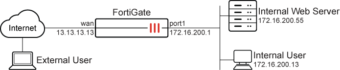
Request initiation: An employee within the office network attempts to access an internal resource using its external IP address.
-
NAT processing: The request is sent to the FortiGate, which recognizes that the destination IP address is its own external IP on the WAN interface.
-
Hairpin NAT: The FortiGate redirects the request back into the internal network, forwarding it to the web server’s internal IP address and allowing the employee to access the internal web server using the external address.
Example
This configuration allows both internal and remote employees to use the same domain name to access the server, such as www.pochiya.com. Hairpin NAT ensures consistency, avoiding confusion and complications in network configurations. This setup is particularly useful for companies that save bookmarks to internal web servers using public domain names in users’ profiles, ensuring access whether connected to the internal LAN or the internet.
In this scenario, the user can access saved bookmarks containing public domain names from both their office computer on the internal network and their personal computer over the internet.
Before continuing, make sure that the port1 and wan interfaces have been configured with valid IP addresses and some publicly accessible domain names are saved as bookmarks in the user profile.
It is assumed that you have administrative access, the FortiGate is incorporated into your network, and the external IP address is the same as the FortiGate wan interface.
The configuration has four steps:
-
Create a VIP: Map the external IP address to the internal IP address.
-
Create a firewall policy for DNAT: Attach the VIP to a firewall policy, allowing external users to access the internal server using the external IP address. See Static virtual IPs for more information.
-
Create a firewall policy for SNAT: Allow internal users to access the external servers using the external IP address. See Static SNAT for more information.
-
Verify the result: Confirm that the employee can access the internal web server using the external address.
To create a VIP in the GUI:
-
Go to Policy & Objects > Virtual IPs or, if Central NAT is enabled, Policy & Objects > DNAT & Virtual IPs.
-
Select the Virtual IP and click Create new.
-
Configure the following:
Field
Value
Name
Internal_WebServer
Interface
any
Type
Static NAT
External IP address/range
13.13.13.13
IPv4 address/range
172.16.200.55
-
Click OK.
To create a firewall policy for DNAT in the GUI:
-
Go to Policy & Objects > Firewall Policy, and click Create New.
-
Configure the following:
Field
Value
Name
wan-lan
Type
Standard
Incoming interface
wan
Outgoing interface
port1
Source
all
Destination
Internal_WebServer
Schedule
always
Service
ALL
Action
ACCEPT
NAT
Enabled
IP pool configuration
Use Outgoing Interface Address
Log allowed traffic
All sessions
-
Click OK.
To create a firewall policy for SNAT in the GUI:
-
Go to Policy & Objects > Firewall Policy, and click Create New.
-
Configure the following:
Field
Value
Name
lan-wan
Type
Standard
Incoming interface
port1
Outgoing interface
wan
Source
all
Destination
all
Schedule
always
Service
ALL
Action
ACCEPT
NAT
Enabled
IP pool configuration
Use Outgoing Interface Address
Log allowed traffic
All sessions
-
Click OK.
To configure the VIP and policies in the CLI:
-
Create the VIP:
config firewall vip edit "Internal_WebServer " set extip 13.13.13.13 set mappedip "172.16.200.55" set extintf "any" next end -
Create firewall policies for DNAT (
wan-lan) and SNAT (lan-wan):config firewall policy edit 2 set name "wan-lan" set srcintf "wan" set dstintf "port1" set action accept set srcaddr "all" set dstaddr "Internal_WebServer" set schedule "always" set service "ALL" set logtraffic all set nat enable next edit 3 set name "lan-wan" set srcintf "port1" set dstintf "wan" set action accept set srcaddr "all" set dstaddr "all" set schedule "always" set service "ALL" set logtraffic all set nat enable next end
To verify the results:
-
Access the internal machine and use the saved bookmark or the external IP address of the internal web server to access it. This should be successful, and the web server should load correctly. From the FortiGate side, this can be verified using the logs and session list
-
On the FortiGate, go to Log & Report > Forward Traffic and double click the desired log entry to view its details, or use the CLI to view the logs:
#execute log filter category 0
#execute log display
1: date=2024-12-05 time=11:43:58 eventtime=1733427838055576829 tz="-0800" logid="0000000013" type="traffic" subtype="forward" level="notice" vd="root" srcip=172.16.200.13 srcport=54134 srcintf="port1" srcintfrole="undefined" dstip=13.13.13.13 dstport=443 dstintf="wan" dstintfrole="undefined" srccountry="Reserved" dstcountry="Reserved" sessionid=5797 proto=6 action="close" policyid=2 policytype="policy" poluuid="1dbc281e-b32c-51ef-f783-7b95542c1baf" policyname="wan-lan" service="HTTPS" trandisp="snat+dnat" tranip=172.16.200.55 tranport=443 transip=172.16.200.1 transport=54134 appcat="unscanned" duration=2 sentbyte=2063 rcvdbyte=1748 sentpkt=8 rcvdpkt=5

If the logs are missing, go to Log & Report > Forward Traffic and increase the time frame to ensure that all pertinent log entries are available.
-
Check session list:
#get system session list | grep 13.13.13.13
PROTO   EXPIRE SOURCE           SOURCE-NAT       DESTINATION      DESTINATION-NAT
tcp     59  	172.16.200.13:3  172.16.200.1:3   13.13.13.13:8    172.16.200.55:3