


Practical overlay examples
Let's continue an example from the previous section, where a site has two Internet connections, plugged into the interfaces "wan1" and "wan2" respectively. We will configure two overlay tunnels to the Hub, one over each Internet transport, named H1_ISP1 and H1_ISP2 respectively. Our list of SD-WAN Members now includes both the underlays ("wan1" "wan2") and the overlays (H1_ISP1, H1_ISP2).
|
|
Here "H1" stands for "Hub 1", just to have our naming ready for a Dual-Hub topology, which is very popular for redundancy reasons. We will discuss this in more detail in Overlay network designs. |
What kind of SD-WAN configuration could we apply, in addition to the examples from the previous section?
Corporate traffic (site-to-site)
-
Corporate traffic - Lowest Cost (SLA) It is common to treat the overlays as a Primary and a Backup, similar to the underlays. Therefore, if we prefer using the ISP1 transport, we will configure an SD-WAN rule matching our corporate (site-to-site) traffic and preferring H1_ISP1 over H1_ISP2, but only as long as it meets the required SLA target (for example,100 ms). If the health of ISP1 path degrades, so that H1_ISP1 overlay can no longer meet the target, the sessions will switchover to H1_ISP2. Once the H1_ISP1 overlay can meet the SLA target again, the sessions will switchover back.
-
Corporate traffic - Best Quality If there is a need to make a VoIP call between two Branch offices, a typical requirement is to select an overlay that provides the best quality at the moment. We can configure an SD-WAN rule to select the best out of the overlays H1_ISP1 and H1_ISP2. If the health of the overlays changes during the call, the audio stream will switchover, ensuring the best possible call experience.
Internet access
The same SD-WAN rule is often used to select between underlays and overlays. To see why, let's talk about different ways of Internet access in the SD-WAN Solution.
-
In the examples presented in the previous section, our applications were steered to the public Internet directly through the underlays ("wan1" and "wan2"). This is known as Direct Internet Access (DIA), because the traffic leaves the corporate boundaries directly at the site edge.
-
An alternative way is known as Remote Internet Access (RIA), in which the traffic is backhauled through a central location (normally through the Hub).
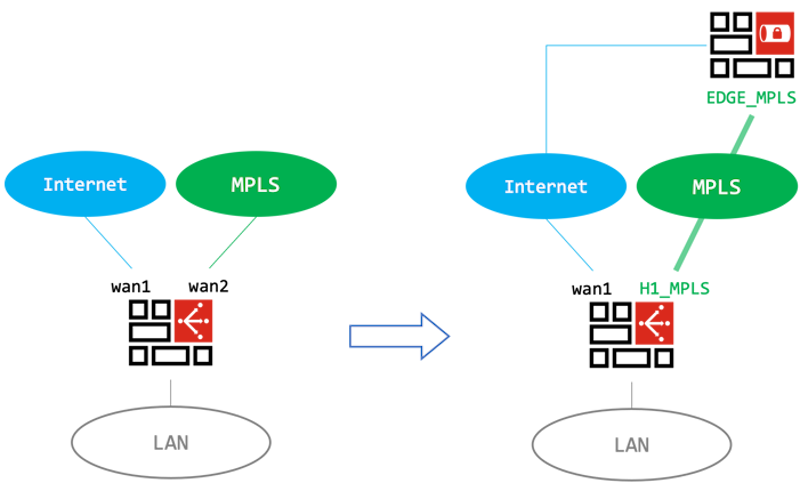
Let's look at another SD-WAN site, where we have one Internet connection (plugged into "wan1") and one MPLS connection (plugged into "wan2"). We will configure two overlay tunnels to the Hub, with one over each transport, but only one of them is relevant for this example: namely, the one over the MPLS transport, named H1_MPLS. The following diagram depicts both the underlay connectivity and the relevant part of the overlay network:
Here is a common SD-WAN strategy for this case:
-
Internet access - Lowest Cost (SLA) Although an MPLS connection may generally provide premium levels of service, the advantage is not straightforward when the destination is on the public Internet. It is often more efficient to breakout to the Internet directly at the site edge (DIA). Furthermore, DIA offloads the central Hub and, last but not least, it is often cheaper (reducing the bandwidth required from the MPLS network). But at the same time, we must guarantee the required SLA targets for business-critical applications.
Therefore, we may configure an SD-WAN rule to match these applications and prefer "wan1" over H1_MPLS, but only as long as it meets the configured SLA target. If the local Internet connection cannot meet the SLA target, the traffic will be backhauled through the H1_MPLS overlay (RIA). As you can see, this is yet another example of the Primary/Backup model, just in this case the selection is between an underlay and an overlay.