


Deploying FortiWLC Virtual Controllers with VMWare ESXi
This section describes the virtual controller deployment procedure on VMWare ESXi. This section includes the following topics:
- Pre-requisites
- Downloading the Virtual Controller PackageFile
- Configuring the Virtual Controller
- Installing the Virtual Controller
- Starting the Virtual Controller
- Recommended VMware ESXi Host Settings
Pre-requisites
For deployment and management of the Virtual Controller, you will need to download any of these VMware suites to the workstation:
- Single ESXi server management − Use VMware vSphere Client.
- Multiple ESXi servers requires vCenter − Advance features are also tied with vCenter which needs separate licenses (vMotion, and so on).
Virtual Controllers can be deployed in these 2 modes in a VMWare setup.
Note: Fortinet recommends that you deploy the Virtual Controllers in the dedicated mode. This mode of deployment achieves the maximum throughput for each Controller model, especially when using the APs in Tunnel mode where all the traffic will be tunneled by the APs to the controller and then to the Network.
The deployed Virtual controllers have a dedicated NIC, vSwitch and vPort Group.
Start the VMware vSphere Client, and log in to the ESXi server. Go to Configuration and click Networking.
As you can see, there are existing 2 VM running on the host, using the same vSwitch0 and same Virtual Machine port Group. The vSwitch is also used by the vKernel Port that is responsible for the ESXi management.
Downloading the Virtual Controller PackageFile
You can download the virtual controller packages from the Fortinet Customer Support website. To access the support website you need a Fortinet Customer Support account.
The file name is, forti-x.x-xbuild-0-x86_64.ova, where x.x-x is the release version number. For example, 8.5.2.
Configuring the Virtual Controller
In this deployment, we will be using an added NIC card with 2 Gig Ethernet ports as shown in the Network Adapters wizard.
The 2 gig interfaces are connected to a Switch that support Link Aggregation (LAG). It is assumed in this procedure that the LAG is created on the switch and has the appropriate VLAN configuration.
- Create a new Virtual Switch: Go to Networking and click AddNetworking…

- Select Virtual Machineand click Next.

Create a vSwitch and assign the dedicated physical NIC. Click Next and provide a label for the vSwitch, for example, FWC-VM-50.
- For VLAN ID, select All (4095), if you are using Trunk port on the switch. Click Next and then Finish to complete the vSwitch creation.

- The vSwitch and a virtual machine port group are created. For example, VM Network 4 port group is created as depicted in this image.

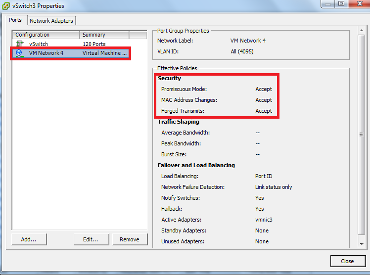
- Click on the vSwitch Properties and select the created port group; click Edit. In this example, the port group is VM Network 4.

- Under the Security tab, select the PromiscuousMode and select Accept from the drop menu and click OK to apply the changes.
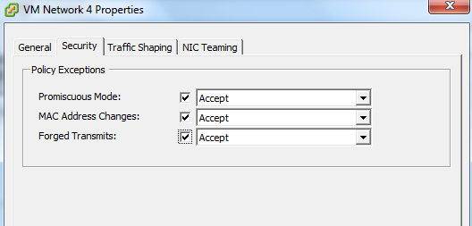
Note: The vSwitch main configuration is set to reject the Promiscuous mode, but the virtual machine port group overwrites the vSwitch configuration and operates in a Promiscuous Mode for the VM Network 4 port group.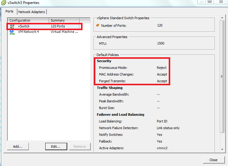
Each vNIC has to be a part of a different Vswitch connected to different physical ports. Now that the structure is ready, start installing the OVA template into the VMware host.
Installing the Virtual Controller
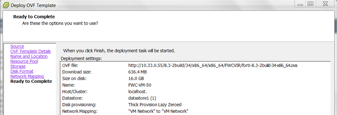
- Go to File and click Deploy OVF Template…in order to start the installation.
- Browse to the location of the OVA template that you downloaded from Fortinet Support page and click Next.

- Click Next and enter a Name for the Virtual Controller, for example, FWC-VM-50 is created as depicted in this image.

-
Configure the Resource Pool and Storage.

Use the default Disk Format - Thick Provisioning Lazy Zereod.
Configure Network Mapping. - ClickFinish in theReady to Completewizard.
The upload and installation of the Virtual Controller will start, the time varies according to the network bandwidth between the vSphere Client and the ESXi Host. You should get aCompleted Successfully message at the end.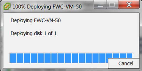

Starting the Virtual Controller
Select the Controller and go to the Console Tab and Start the VM by clicking on the Power On button or (Ctrl+b). The Virtual Controller will start and you will see the entire startup message that you will typically found in a Hardware Controller.
The first boot might take few minutes longer to boot up if no DHCP server is available as the controller will try to get an IP address from the DHCP server. Please refer to the Controller SD documentation to complete the controller installation.
Recommended VMware ESXi Host Settings
Fortinet recommends the following VM configurations and global host settings for enhanced Controller performance.
VM Configuration Settings
-
CPU affinity - In servers where the available physical cores (i.e. half of HT CPUs) are more than the required cores for Controllers, set the CPU affinity such that no two vCPUs are scheduled on the same physical core by the VMKernel.
To set the CPU range, go to Edit Settings ->Virtual Hardware -> CPU -> Scheduling Affinity.
- Latency Sensitivity - Set the Latency sensitivity to High, to do so, go to Edit Settings -> VM Options -> Advanced -> Latency Sensitivity.
- Virtual NIC settings - Disable virtual interrupt coalescing, to do so, go to Edit Settings -> Options tab -> Advanced -> Configuration Parameters and add an entry for ethernetX.coalescingScheme with the value disabled.
Global Host Settings
-
Physical NIC settings – Disable the interrupt moderation/coalescing. Run the esxcli system module parameters set -m ixgbe -p "InterruptThrottleRate=0" CLI command.
This is applicable to Intel 10G with ixgbe driver, that is, chipsets Intel 82599 and is not applicable or i40en based drivers. Run the esxcli network nic list CLI command to find the list of drivers.
- Set the /Net/MaxNetifTxQueueLen global parameter to 10000 (default is 2000). Run the esxcli system settings advanced set -o /Net/MaxNetifTxQueueLen -i=10000 CLI command.
- Set the /Net/NetVMTxType global parameter to 3 (applicable only for ESXi 6.5). Run the esxcli system settings advanced set -o /Net/NetVMTxType -i=3 CLI command.
This allocates multiple Tx world, that is, 1 per queue.
These are the parameters for different Controller models.
|
Parameters |
FWC-VM-50 |
FWC-VM-200 |
FWC-VM-500 (10G) |
FWC-VM-1000 |
FWC-VM-3000 |
FWC-VM-500-(1G) |
|---|---|---|---|---|---|---|
|
CPU affinity |
Yes |
Yes |
Yes |
Yes |
No |
Yes |
|
Latency Sensitivity |
High |
High |
High |
High |
High |
High |
|
Virtual NIC settings (Disable interrupt coalescing) |
Yes |
Yes |
Yes |
Yes |
No |
Yes |
|
/Net/MaxNetifTxQueueLen |
1000 |
1000 |
10000 |
10000 |
10000 |
1000 |
|
/Net/NetVMTxType (for ESXi 6.5 and above) |
1 |
1 |
3 |
3 |
3 |
1 |