


Deploying MCLAG topologies
This section covers the following topics:
- Dual-homed servers connected to a pair of FortiSwitch units using an MCLAG
- Multi-tiered MCLAG with HA-mode FortiGate units
- HA-mode FortiGate units in different sites
- Interconnecting FortiLink fabrics
Dual-homed servers connected to a pair of FortiSwitch units using an MCLAG
To configure a multichassis LAG, you need to configure FortiSwitch 1 and FortiSwitch 2 as MCLAG peer switches before creating a two-port LAG. See Transitioning from a FortiLink split interface to a FortiLink MCLAG. Then you set up two MCLAGs towards the servers, each MCLAG using one port from each FortiSwitch unit.
This topology is also supported when the FortiGate unit is in HA mode.
NOTE:
- On the global switch level,
mclag-stp-awaremust be enabled, and STP must be enabled on all ICL trunks. They are both enabled by default. - Fortinet recommends using at least two links for ICL redundancy.
NOTE: If you are going to use IGMP snooping with an MCLAG topology:
- On the global switch level,
mclag-igmpsnooping-awaremust be enabled. It is enabled by default. - The
mcast-snooping-flood-trafficandigmp-snooping-flood-reportssettings must be disabled on the ISL and FortiLink trunks; but themcast-snooping-flood-trafficandigmp-snooping-flood-reportssettings must be enabled on ICL trunks. These settings are enabled by default. - IGMP proxy must be enabled.

Step 1: Ensure the MCLAG ICL is already configured between FortiSwitch 1 and FortiSwitch 2.
diagnose switch-controller switch-info mclag icl
Step 2: For each server, configure a trunk with MCLAG enabled. For server 1, select port10 on FortiSwitch 1 and FortiSwitch 2. For server 2, select port15 on FortiSwitch 1 and FortiSwitch 2.
For details, refer to MCLAG trunks.
Step 3: Verify the MCLAG configuration.
diagnose switch-controller switch-info mclag list
Multi-tiered MCLAG with HA-mode FortiGate units
Use the following procedure to deploy tier-2 and tier-3 MCLAG peer groups from the FortiGate switch controller without the need for direct console access to the FortiSwitch units.

NOTE:
-
Fortinet recommends using at least two links for ICL redundancy.
- Before FortiOS 6.2.0, when using HA-mode FortiGate units to manage FortiSwitch units, the HA mode must be active-passive. Starting in FortiOS 6.2.0, the FortiGate HA mode can be either active-passive or active-active.
-
In this topology, you must use the
auto-isl-port-groupsetting as described in the following configuration example. This setting instructs the switches to group ports from MCLAG peers together into one MCLAG when the inter-switch link (ISL) is formed. - The
auto-isl-port-groupsetting must be done directly on the FortiSwitch unit. -
On the global switch level,
mclag-stp-awaremust be enabled, and STP must be enabled on all ICL trunks. They are both enabled by default.
NOTE: If you are going to use IGMP snooping with an MCLAG topology:
- On the global switch level,
mclag-igmpsnooping-awaremust be enabled. It is enabled by default. - The
mcast-snooping-flood-trafficandigmp-snooping-flood-reportssettings must be disabled on the ISL and FortiLink trunks; but themcast-snooping-flood-trafficandigmp-snooping-flood-reportssettings must be enabled on ICL trunks. These settings are enabled by default. - IGMP proxy must be enabled.
To create a three-tier FortiLink MCLAG topology, use FortiOS 6.2.3 GA or later and FortiSwitchOS 6.2.3 GA or later.
Tier-1 MCLAG
Wire the two core FortiSwitch units to the FortiGate devices. To configure the FortiSwitch units in the core, see Transitioning from a FortiLink split interface to a FortiLink MCLAG.
Tier-2 and Tier-3 MCLAGs

- Connect only the tier-2 MCLAG FortiSwitch units 3 and 4 to the core units 1 and 2 (leaving the other switches in Closet 1 disconnected). Wait until they are discovered and authorized (authorization must be done manually if auto-authorization is disabled).
- Using the FortiGate CLI, assign the LLDP profile “default-auto-mclag-icl” to the ports that should form the MCLAG ICL in the tier-2 MCLAG switches 3 and 4. For example:
FGT_Switch_Controller # config switch-controller managed-switch
FGT_Switch_Controller (managed-switch) # edit FS1E48T419000051
FGT_Switch_Controller (FS1E48T419000051) # config ports
FGT_Switch_Controller (ports) # edit port49
FGT_Switch_Controller (port49) # set lldp-profile default-auto-mclag-icl
FGT_Switch_Controller (port49) # end
FGT_Switch_Controller (FS1E48T419000051) # end
- For each tier-2 MCLAG peer group, add an
auto-isl-port-groupfor the tier-2 MCLAG switches on both switch 1 and switch 2:config switch auto-isl-port-group
edit tier2-closet-1
set members port1
next
edit tier2-closet-2
set members port2
next
end
This configuration is done directly in the FortiSwitch CLI (or by binding a custom script using custom commands on the FortiGate device. See Executing custom FortiSwitch scripts.
If there is not a tier-3 MCLAG, skip to step 7.
- Wire the tier-3 MCLAG switches 5, 6, 7, and 8. Wait until they are discovered and authorized (authorization must be done manually if auto-authorization is disabled).
- For each tier-3 MCLAG peer group, add two
auto-isl-port-groups for the tier-3 MCLAG switches on both switch 3 and switch 4:config switch auto-isl-port-group
edit tier-2-closet-<1>-downlink-trunk-A
set member <port_name>
next
edit tier-2-closet-<1>-downlink-trunk-B
set member <port_name>
next
end
This configuration is done directly in the FortiSwitch CLI (or by binding a custom script using custom commands on the FortiGate device. See Executing custom FortiSwitch scripts.
- Using the FortiGate CLI, assign the LLDP profile “default-auto-mclag-icl” to the ports that should form the ICL in the tier-3 MCLAG peers switches 5 and 6 and switches 7 and 8. For example:
FGT_Switch_Controller # config switch-controller managed-switch
FGT_Switch_Controller (managed-switch) # edit FS1E48T419000051
FGT_Switch_Controller (FS1E48T419000051) # config ports
FGT_Switch_Controller (ports) # edit port49
FGT_Switch_Controller (port49) # set lldp-profile default-auto-mclag-icl
FGT_Switch_Controller (port49) # end
FGT_Switch_Controller (FS1E48T419000051) # end
- Connect the access switches to the MCLAG peer groups, and the inter-switch links are formed automatically. Wait until they are discovered and authorized (authorization must be done manually if auto-authorization is disabled).
- Wire only the tier-2 MCLAG FortiSwitch units from Closet 2 (leaving the other switches in Closet 2 disconnected). Wait until they are discovered and authorized (authorization must be done manually if auto-authorization is disabled). Return to step 3 to complete the process for Closet 2.
- All FortiSwitch units are now authorized, and all MCLAG peer groups are enabled. Proceed with the configuration of the FortiSwitch units by assigning VLANs to the access ports and any other functionality required.
HA-mode FortiGate units in different sites
There are two sites in this topology, each with a FortiGate unit. The two sites share the FortiGate units in active-passive HA mode. The FortiGate units use the FortiSwitch units in FortiLink mode as the heartbeat connections because of limited physical connections between the two sites.
FortiOS 6.4.2 or higher and FortiSwitchOS 6.4.2 or higher are required.
Refer to the other network topologies in Deploying MCLAG topologies.
NOTE: Fortinet recommends using at least two links for ICL redundancy.

The following steps are an example of how to configure this topology:
- Disconnect the physical connections between the two sites.
- On Site 1:
- Use the FortiGate unit to establish the FortiLinks on Site 1. See Configuring FortiLink.
- Enable the MCLAG-ICL on the core switches of Site 1. See Transitioning from a FortiLink split interface to a FortiLink MCLAG.
- Enable the HA mode and set the heartbeat ports on FortiGate-1. FortiGate port1 and port2 are used as HA heartbeat ports in this example. For example,
set hbdev "port1" 242 "port2" 25. - Create a switch VLAN or VLANs dedicated to the FortiGate HA heartbeats between the two FortiGate units. For example:
config system interface
edit "hb1"
set vdom "vdom name"
set vlanid 998
next
edit "hb2"
set vdom "vdom name"
set vlanid 999
next
end
- Under the
config switch-controller managed-switchcommand, set the native VLAN of the switch ports connected to the heartbeat ports using the VLAN created in step 2d.
In this example, you need to assign port1 of core-switch1 to vlan998 and connect port1 of the active FortiGate unit to port1 of core-switch1. Then you need to assign port1 of core-switch2 to vlan999 and connect port2 of the active FortiGate unit to port1 of core-switch2.config switch-controller managed-switch
edit <site1-core-switch1>
edit "port1"
set vlan "hb1"
next
end
edit <site1-core-switch2>
edit "port1"
set vlan "hb2"
next
end
- Make sure all FortiLinks are up.
- On Site 2:
- Configure Site 2 using the same configuration as step 2, except for the HA priority.
- Make sure all FortiLinks are up.
- Disconnect the physical connections for the FortiGate HA and FortiLink interface on Site 2.
- Connect the cables between the two pairs of core switches in Site 1 and Site 2.
- On both sites:
- On the MCLAG Peer Group switches at Site 1, use the
config switch auto-isl-port-groupcommand in the FortiSwitch CLI to group the ports to Site 2. See Deploying MCLAG topologies. - On the MCLAG Peer Group switches at Site 2 , use the
config switch auto-isl-port-groupcommand in the FortiSwitch CLI to group the ports to Site 1. See Deploying MCLAG topologies. - Make sure all the FortiLinks are up.
- On the MCLAG Peer Group switches at Site 1, use the
- Connect the FortiGate HA and FortiLink interface connections on Site 2.
- Check the configuration:
- On both sites, enter the
get system ha statuscommand on the FortiGate unit to check the HA status. - On the active (master) FortiGate unit, enter the
execute switch-controller get-conn-statuscommand to check the FortiLink state.
- On both sites, enter the
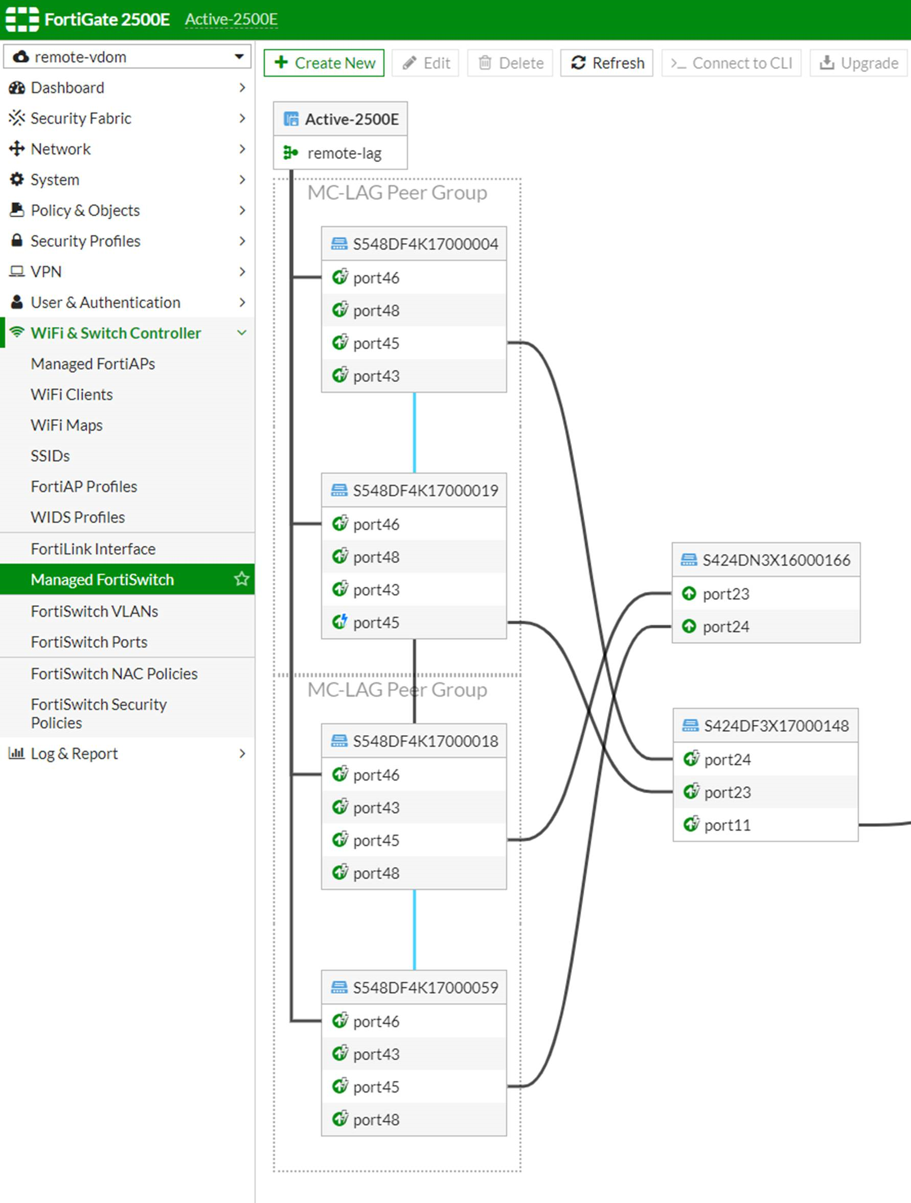
- In the GUI, the example configuration looks like the following:
Interconnecting FortiLink fabrics
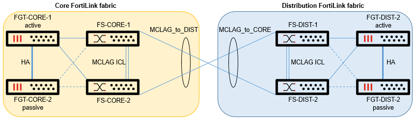
Each FortiLink fabric is a set of FortiSwitch units controlled by a FortiGate device. When you interconnect FortiLink fabrics, each FortiGate device manages its own FortiSwitch units. The FortiLink fabric interconnection points are seen as access ports from each FortiGate unit; no inter-switch links are formed.
In this example:
-
The interconnecting ports (port15) on FS-CORE-1, FS-CORE-2, FS-DIST-1, and FS-DIST-2 have the LLDP profile set to
defaultwithauto-isldisabled. -
Optionally, you can disable the management of FS-DIST-1 and FS-DIST-2 by the FGT-CORE switch controller.
-
FGT-CORE-1 and FGT-CORE-2 have the MCLAG trunk
MCLAG_to_DIST. -
FGT-DIST-1 and FGT-DIST-2 have the MCLAG trunk
MCLAG_to_CORE. -
The allowed VLANs on the
MCLAG_to_DISTandMCLAG_to_COREtrunks match.
This topology requires the following:
-
Disable
auto-islon the interconnection links to avoid one FortiGate device discovering or managing FortiSwitch units that should be discoverd and managed by the other FortiGate device. -
Optionally, on one FortiGate device, disable discovery for the FortiSwitch serial numbers managed by the other FortiGate device.
-
Configure matching native VLANs and allowed VLANs on both sides to allow communication between FortiLink fabrics.
-
The VLAN IDs must match, but the names can be different.
Deployment steps
-
Deploy each FortiGate device and respective FortiSwitch units separately. See Transitioning from a FortiLink split interface to a FortiLink MCLAG.
-
(Optional) Disable discovery for the FortiSwitch units from the other FortiGate device.
-
Assign the “default” LLDP profile to the interconnecting ports. See Configuring ports using the GUI.
-
Create the MCLAG trunk for the interconnection. See Adding 802.3ad link aggregation groups (trunks).
-
Assign matching native VLANs and allowed VLANs to the MCLAG trunk. See Configuring ports using the GUI.
-
Connect the cables to interconnect the FortiLink fabrics.
Configuration example
|
|
This configuration example assumes that each FortiLink fabric has been deployed already. |
To configure the core FortiLink fabric:
-
Configure the FortiLink interface that will be used to interconnect the two FortiLink fabrics.
config system interface
edit "INTERCON"
set vdom "root"
set ip 10.255.255.1 255.255.255.252
set allowaccess ping ssh
set color 20
set interface "fortilink"
set vlanid 500
next
end
-
Assign the “default” LLDP profile to the switch ports and configure the MCLAG trunk toward the core FortiLink fabric (FS-CORE-1 and FS-CORE-2).
config switch-controller managed-switch
edit "FS-CORE-1"
config ports
edit "port15"
set port-owner "MCLAG_to_DIST"
set lldp-profile "default"
next
edit "port16"
set port-owner "MCLAG_to_DIST"
set lldp-profile "default"
next
edit "MCLAG_to_DIST"
set vlan "INTERCON"
set type trunk
set mode lacp-active
set mclag enable
set members "port15" "port16"
next
end
next
end
config switch-controller managed-switch
edit "FS-CORE-2"
config ports
edit "port15"
set port-owner "MCLAG_to_DIST"
set lldp-profile "default"
next
edit "port16"
set port-owner "MCLAG_to_DIST"
set lldp-profile "default"
next
edit "MCLAG_to_DIST"
set vlan "INTERCON"
set type trunk
set mode lacp-active
set mclag enable
set members "port15" "port16"
next
end
next
end
-
Optionally, prevent the core FortiGate devices from discovering the distribution FortiSwitch units.
config switch-controller global
set disable-discovery "FS-DIST-1" "FS-DIST-2"
end
To configure the distribution FortiLink fabric:
-
Configure the FortiLink interface that will be used to interconnect the two FortiLink fabrics.
config system interface
edit "INTERCON"
set vdom "root"
set ip 10.255.255.2 255.255.255.252
set allowaccess ping ssh
set color 20
set interface "fortilink"
set vlanid 500
next
end
-
Assign the “default” LLDP profile to the switch ports and configure the MCLAG trunk toward the core FortiLink fabric (FS-DIST-1 and FS-DIST-2).
config switch-controller managed-switch
edit "FS-DIST-1"
config ports
edit "port15"
set port-owner "MCLAG_to_CORE"
set lldp-profile "default"
next
edit "port16"
set port-owner "MCLAG_to_CORE"
set lldp-profile "default"
next
edit "MCLAG_to_CORE"
set vlan "INTERCON"
set type trunk
set mode lacp-active
set mclag enable
set members "port15" "port16"
next
end
next
end
config switch-controller managed-switch
edit "FS-DIST-2"
config ports
edit "port15"
set port-owner "MCLAG_to_CORE"
set lldp-profile "default"
next
edit "port16"
set port-owner "MCLAG_to_CORE"
set lldp-profile "default"
next
edit "MCLAG_to_CORE"
set vlan "INTERCON"
set type trunk
set mode lacp-active
set mclag enable
set members "port15" "port16"
next
end
next
end
-
Optionally, prevent the distribution FortiGate devices from discovering the core FortiSwitch units.
config switch-controller global
set disable-discovery "FS-CORE-1" "FS-CORE-2"
end