


Global system and switch settings
This chapter covers the following topics:
- Configuration file settings
- SSL configuration
- Configuration file revisions
- IP conflict detection
- Port flap guard
- Link monitor
- Unicast hashing
- Cut-through switching mode
- Enabling packet forwarding
- ARP timeout value
- Power over Ethernet configuration
- Creating a schedule
- Overlapping subnets
- Configuring PTP transparent-clock mode
- Configuring auto topology
Configuration file settings
You can set preferences for saving configuration files:
- Go to System > Config > Backup.
- Select one of the Configuration Save options:
- Automatically Save—The system automatically saves the configuration after each change.
- Manually Save—You must manually save configuration changes from the Backup link on the System > Dashboard.
-
Manually Save and Revert Upon Timeout—You must manually save configuration changes. The system reverts to the saved configuration after a timeout. You can set the timeout using the CLI:
config system globalset cfg-revert-timeout <integer>
- If you select Revision Backup on Logout, the FortiSwitch unit creates a configuration file each time a user logs out.
- If you select Revision Backup on Upgrade, the FortiSwitch unit creates a configuration file before starting a system upgrade.
- Select Update.
SSL configuration
You can set strong cryptography and select which certificates are used by the FortiSwitch unit.
Using the GUI:
- Go to System > Config > SSL.
- Select Strong Crypto to use strong cryptography for HTTPS and SSH access.
- Select one of the 802.1x certificate options:
- Entrust_802.1x—This certificate is embedded in the firmware and is the same on every unit (not unique). It has been signed by a public CA. This is the default certificate for 802.1x authentication.
- Fortinet_Factory—This certificate is embedded in the hardware at the factory and is unique to this unit. It has been signed by a proper CA.
- Fortinet_Factory2—This certificate is embedded in the hardware at the factory and is unique to this unit. It has been signed by a proper CA.
- Fortinet_Firmware—This certificate is embedded in the firmware and is the same on every unit (not unique). It has been signed by a proper CA. It is not recommended to use it for server-type functionality since any other unit could use this same certificate to spoof the identity of this unit.
- Select one of the 802.1x certificate authority (CA) options:
- Entrust_802.1x_CA—Select this CA if you are using 802.1x authentication.
- Entrust_802.1x_G2_CA—Select this CA if you want to use the Google Internet Authority G2.
- Entrust_802.1x_L1K_CA—Select this CA if you want to use http://ocsp.entrust.net.
- Fortinet_CA—Select this CA if you want to use the factory-installed certificate.
- Fortinet_CA2—Select this CA if you want to use the factory-installed certificate.
- Select one of the GUI HTTPS certificate options:
- Entrust_802.1x—This certificate is embedded in the firmware and is the same on every unit (not unique). It has been signed by a public CA.
- Fortinet_Factory—This certificate is embedded in the hardware at the factory and is unique to this unit. It has been signed by a proper CA.
- Fortinet_Factory2—This certificate is embedded in the hardware at the factory and is unique to this unit. It has been signed by a proper CA.
- Fortinet_Firmware—This certificate is embedded in the firmware and is the same on every unit (not unique). It has been signed by a proper CA. It is not recommended to use it for server-type functionality since any other unit could use this same certificate to spoof the identity of this unit.
- Select Update.
Using the CLI:
config system global
set strong-crypto {enable | disable}
set 802.1x-certificate {Entrust_802.1x | Fortinet_Factory | Fortinet_Factory2 | Fortinet_Firmware}
set 802.1x-ca-certificate {Entrust_802.1x_CA | Entrust_802.1x_G2_CA | Entrust_802.1x_L1K_CA | Fortinet_CA | Fortinet_CA2}
set admin-server-cert {self-sign | Entrust_802.1x | Fortinet_Factory | Fortinet_Factory2 | Fortinet_Firmware}
end
Configuration file revisions
You can select a configuration file revision to revert to.
Using the GUI:
- Go to System > Config > Revisions.
The system displays a new page with an entry for each configuration file revision. - When you select a revision, the following commands are available:
- Deselect All—deselect all selected revisions.
- Delete—deletes the selected revision file.
- Revert—reverts the system configuration to the selected revision.
- Upload—uploads the selected revision file to your local machine.
- If you select two revision files, you can select Diff to display the differences between the two files.
Using the CLI:
Use the following command to display the list of configuration file revisions:
execute revision list config
The FortiSwitch unit assigns a numerical ID to each configuration file. To display a particular configuration file contents, use the following command and specify the ID of the configuration file:
execute revision show config id <ID number>
The following example displays the list of configuration file revisions:
# execute revision list config

ID TIME ADMIN FIRMWARE VERSION COMMENT
1 2015-08-31 11:11:00 admin V3.0.0-build117-REL0 Automatic backup (session expired)
2 1969-12-31 16:06:29 admin V3.0.0-build150-REL0 baseline
3 2015-08-31 15:19:31 admin V3.0.0-build150-REL0 baseline
4 2015-08-31 15:28:00 admin V3.0.0-build150-REL0 with admin timeout
The following example displays the configuration file contents for revision ID 62:
# execute revision show config id 62

#config-version=FS1D24-3.04-FW-build171-160201:opmode=0:vdom=0:user=admin
#conf_file_ver=1784779075679102577
#buildno=0171
#global_vdom=1
config system global
   set admin-concurrent enable
       ...
   (output truncated)
IP conflict detection
IP conflicts can occur when two systems on the same network are using the same IP address. The FortiSwitch unit monitors the network for conflicts and raises a system log message and an SNMP trap when it detects a conflict.
The IP conflict detection feature provides two methods to detect a conflict. The first method relies on a remote device to send a broadcast ARP (Address Resolution Protocol) packet claiming ownership of a particular IP address. If the IP address in the source field of that ARP packet matches any of the system interfaces associated with the receiving FortiSwitch system, the system logs a message and raises an SNMP trap.
For the second method, the FortiSwitch unit actively broadcasts gratuitous ARP packets when any of the following events occurs:
- System boot-up
- Interface status changes from down to up
- IP address change
If a system is using the same IP address, the FortiSwitch unit receives a reply to the gratuitous ARP. If it receives a reply, the system logs a message.
Configuring IP conflict detection
IP conflict detection is enabled on a global basis. The default setting is enabled.
Using the GUI:
- Go to Network > Settings.
- Select Enable IP Conflict Detection.
- Select Apply.
Using the CLI:
config system global
set detect-ip-conflict <enable|disable>
Viewing IP conflict detection
If the system detects an IP conflict, the system generates the following log message:
IP Conflict: conflict detected on system interface mgmt for IP address 10.10.10.1
Port flap guard
A flapping port is a port that changes status rapidly from up to down. A flapping port can create instability in protocols such as STP. If a port is flapping, STP must continually recalculate the role for each port. Flap guard also prevents unwanted access to the physical ports.
The port flap guard detects how many times a port changes status during a specified number of seconds, and the system shuts down the port if necessary. You can manually reset the port and restore it to the active state.
Retaining the triggered state
When the flap guard is triggered, the status for the port is shown as “triggered” in the output of the diagnose flapguard status command. By default, rebooting the switch resets the state of the flap guard and removes the “triggered” state. You can change the setting so that the triggered state remains after a switch is rebooting until the port is reset. See Resetting a port.
Using the GUI:
- Go to Switch > Flap Guard.

- Select Retain Triggered State Across Reboot.
- Select Update to save the change.
Using the CLI:
config switch global
set flapguard-retain-trigger enable
end
Configuring the port flap guard
The port flap guard is configured and enabled on each port. The default setting is disabled.
The flap rate counts how many times a port changes status during a specified number of seconds. The range is 1 to 30 with a default setting of 5.
The flap duration is the number of seconds during which the flap rate is counted. The range is 5 to 300 seconds with a default setting of 30 seconds.
The flap timeout (CLI only) is the number of minutes before the flap guard is reset. The range is 0 to 120 minutes. The default setting of 0 means that there is no timeout.
NOTE:
- If a triggered port times out while the switch is in a down state, the port is initially in a triggered state until the switch has fully booted up and calculated that the timeout has occurred.
- The following models do not store time across reboot; therefore, any triggered port is initially in a triggered state until the switch has fully booted up—at which point the trigger is cleared:
- FS-1xxE
- FS-2xxD/E
- FS-4xxD
- FS-4xxE
Using the GUI:
- Go to Switch > Port > Physical.
- Select a port.
- Select Edit.
- Under Flap Guard, select Enable.

- Enter values for Flap Duration (Seconds) and Flap Rate.
- Select Update to save the changes.
Using the CLI:
config switch physical-port
edit <port_name>
set flapguard {enabled | disabled}
set flap-rate <1-30>
set flap-duration <5-300 seconds>
set flap-timeout <0-120 minutes>
end
For example:
config switch physical-port
edit port10
set flapguard enabled
set flap-rate 15
set flap-duration 100
set flap-timeout 30
end
Resetting a port
After the flap guard detects that a port is changing status rapidly and the system shuts down the port, you can reset the port and restore it to service.
Using the GUI:
- Go to Switch > Port > Physical.
- Select the port that was shut down.
- Select Reset.
Using the CLI:
execute flapguard reset <port_name>
For example:
execute flapguard reset port15
Viewing the port flap guard configuration
Use the following command to check if the flap guard is enabled on a specific port:
show switch physical-port <port_name>
For example:
show switch physical-port port10
Use the following command to display the port flap guard information for all ports:
diagnose flapguard status
Link monitor
You can monitor the link to a server. The FortiSwitch unit sends periodic ping messages to test that the server is available. In the CLI, you can use both IPv4 and IPv6 addresses.
Configuring the link monitor
Using the GUI:
- Go to Router > Config > Link Probes.
- Select Add Probe to create a new probe.
- Enter an IP address for the Gateway IP.
- Configure the other fields as required (see the table in this section for field descriptions).
- Select Add to create the probe.
Using the CLI:
config system link-monitor
edit <link monitor name>
set addr-mode {ipv4 | ipv6}
set srcintf <string>
set protocol {arp | ping}
set gateway-ip <IPv4 address>
set gateway-ip6 <IPv6 address>
set source-ip <IPv4 address>
set source-ip6 <IPv6 address>
set interval <integer>
set timeout <integer>
set failtime <integer>
set recoverytime <integer>
set update-static-route {enable | disable}
set status {enable | disable}
next
end
|
Variable |
Description |
|---|---|
|
<link monitor name> |
Enter the link monitor name. |
|
addr-mode {ipv4 | ipv6} |
Select whether to use IPv4 or IPv6 addresses. The default is IPv4 addresses. |
|
srcintf <string> |
Interface where the monitor traffic is sent. |
|
protocol {arp | ping} |
Protocols used to detect the server. Select ARP or ping. |
|
gateway-ip <IPv4 address> |
Gateway IPv4 address used to PING the server. This option is available only when |
|
gateway-ip6 <IPv6 address> |
Gateway IPv6 address used to PING the server. This option is available only when |
|
source-ip <IPv4 address> |
Source IPv4 address used in packet to the server. This option is available only when |
|
source-ip6 <IPv6 address> |
Source IPv6 address used in packet to the server. This option is available only when |
|
interval <integer> |
Detection interval in seconds. The range is 1-3600. |
|
timeout <integer> |
Detect request timeout in seconds. The range is 1-255. |
|
failtime <integer> |
Number of retry attempts before bringing the server down. The range is 1-10. |
|
recoverytime <integer> |
Number of retry attempts before bringing the server up. The range is 1-10. |
|
update-static-route {enable | disable} |
Enable or disable update static route. The default is enabled. |
|
status {enable | disable} |
Enable or disable link monitor administrative status. The default is enabled. |
Unicast hashing
You can configure the trunk hashing algorithm for unicast packets to use the source port:
config switch global
set trunk-hash-unicast-src-port {enable | disable}
end
Cut-through switching mode
By default, all FortiSwitch models use the store-and-forward technique to forward packets. This technique waits until the entire packet is received, verifies the content, and then forwards the packet.
The FS-1024D, FS-1048D, and FS-3032D models also have a cut-through switching mode to reduce latency. This technique forwards the packet as soon as the switch receives it.
NOTE: For the FS-3032D model, the cut-through switching mode is not supported on split ports.
To change the switching mode for the main buffer for these three models, use the following commands:
config switch global
set packet-buffer-mode {store-forward | cut-through}
end
NOTE: Changing the switching mode might stop traffic on all ports during the change.
Enabling packet forwarding
NOTE: These commands apply only to the 200 Series and 400 Series.
If you want to use layer-3 interfaces and IGMP snooping on certain FortiSwitch models, you must enable the forwarding of reserved multicast packets and IPv6 neighbor-discovery packets to the CPU. These features are enabled by default.
config switch global
set reserved-mcast-to-cpu {enable | disable}
set neighbor-discovery-to-cpu {enable | disable}
end
ARP timeout value
By default, ARP entries in the cache are removed after 180 seconds. Use the following commands to change the default ARP timeout value:
config system global
set arp-timeout <seconds>
end
For example, to set the ARP timeout to 1,000 seconds:
config system global
set arp-timeout 1000
end
Power over Ethernet configuration
Power over Ethernet (PoE) describes any system that passes electric power along with data on twisted pair Ethernet cabling. Doing this allows a single cable to provide both data connection and electric power to devices (for example, wireless access points, IP cameras, and VoIP phones).
|
|
PoE is only available on models with the POE suffix in the model number (for example, FS-108E-POE).
|
Using the GUI:
- Go to Switch > POE.
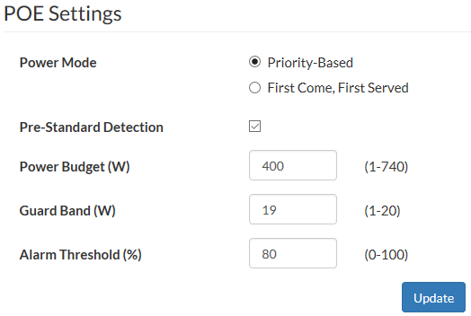
- Set the PoE power mode to priority based or first-come, first-served.
When power to PoE ports is allocated by priority, lower numbered ports have higher priority so that port 1 has the highest priority. When more power is needed than is available, higher numbered ports are disabled first.
When power to PoE ports is allocated by first-come, first-served (FCFS), connected PoE devices receive power, but new devices do not receive power if there is not enough power.
If both priority power allocation and FCFS power allocation are selected, the physical port setting takes precedence over the global setting.
- Enable or disable PoE pre-standard detection.

PoE pre-standard detection is a global setting for the following FortiSwitch models:
FSR-112D-POE, FS-548D-FPOE, FS-524D-FPOE, FS-108D-POE, FS-224D-POE, FS-108E-POE, FS-108E-FPOE, FS-124E-POE, and FS-124E-FPOE.
For the other FortiSwitch PoE models, PoE pre-standard detection is set on each port.
- Set the maximum power budget in Watts.
- Enter the power in Watts to reserve in case of a spike in PoE consumption.
- Enter the threshold (a specified percentage of the total power budget) above which an alarm event is generated.
If your FortiSwitch unit has a PoE sensor, you can set an alarm for when the current power budget exceeds a specified percentage of the total power budget. When this threshold is exceeded, log messages and SNMP traps are generated. The default threshold is 80 percent. - Select Update.
Using the CLI:
config switch global
set poe-alarm-threshold <0-100 percent>
set poe-power-mode {first-come-first-serverved | priority}
set poe-guard-band <1-20 Watts>
set poe-pre-standard-detect {disable | enable}
set poe-power-budget <1-740 Watts>
end
Creating a schedule
Use schedules to control when policies are enforced. For example, you can use a schedule to control when an access control list policy is enforced.
NOTE: If the status of an ACL policy is inactive, the schedule is ignored.
You can create a one-time schedule, a recurring schedule, or a group schedule:
- Use a one-time schedule when you want a policy enforced for a specified period.
- Use a recurring schedule when you want a policy enforced for specified hours and days every week.
- Use a group schedule to combine one-time schedules and recurring schedules.
To create a one-time schedule:
config system schedule onetime
edit <schedule_name>
set start <time_date>
set end <time_date>
end
For example:
config system schedule onetime
edit schedule1
set start 07:00 2019/03/22
set end 07:00 2019/03/29
end
To create a recurring schedule:
config system schedule recurring
edit <schedule_name>
set day {monday | tuesday | wednesday | thursday | friday | saturday | sunday}
set start <time>
set end <time>
end
For example:
config system schedule recurring
edit schedule2
set day monday wednesday friday
set start 07:00
set end 08:00
end
To create a group schedule:
config system schedule group
edit <schedule_group_name>
set member <schedule_name1> <schedule_name2> ...
end
For example:
config system schedule group
edit group1
set member schedule1 schedule2
end
Overlapping subnets
You can use the set allow-subnet-inteface command to allow two interfaces to include the same IP address in the same subnet. The command applies only between the mgmt interface and an internal interface.
NOTE: Different interfaces cannot have overlapping IP addresses or subnets. The same IP address can be used on different switches.
For example:
config system global
set admintimeout 480
set allow-subnet-overlap enable
set auto-isl enable
end
config system interface
edit "mgmt"
set ip 172.16.86.112 255.255.255.0
set allowaccess ping https http ssh snmp telnet
set type physical
set alias "test"
set snmp-index 27
next
edit "internal"
set ip 10.0.1.112 255.255.255.0
set allowaccess ping
set type physical
set alias "testing-2"
set snmp-index 26
next
end
Configuring PTP transparent-clock mode
Use Precision Time Protocol (PTP) transparent-clock mode to measure the overall path delay for packets in a network to improve the time precision. There are two transparent-clock modes:
- End-to-end measures the path delay for the entire path
- Peer-to-peer measures the path delay between each pair of nodes
Use the following steps to configure PTP transparent-clock mode:
- Configure the global PTP settings.
By default, PTP is disabled. - Enable the PTP policy.
By default, the PTP policy is disabled. - Apply the PTP policy to a port.
To configure the global PTP settings:
config switch ptp settings
set mode {disable | transparent-e2e | transparent-p2p}
end
To enable the PTP policy:
config switch ptp policy
edit {default | <policy_name>}
set status {enable | disable}
next
end
To apply the PTP policy to a port:
config switch interface
edit <port_name>
set ptp-policy {default | <policy_name>}
next
end
For example:
config switch ptp settings
set mode transparent-e2e
end
config switch ptp policy
edit default
set status enable
next
end
config switch interface
edit port12
set ptp-policy default
next
end
Configuring auto topology
Use the auto topology feature to automatically form an inter-switch link (ISL) between two switches. You need to enable the feature and specify the mgmt-vlan. The mgmt-vlan is the VLAN to use for the native VLAN on ISL ports and the native VLAN on the internal switch interface.
NOTE: Do not use the same VLAN for the mgmt-vlan and an existing switch virtual interface (SVI).
config switch auto-network
set mgmt-vlan <1-4094>
set status {enable | disable}
end
For example:
config switch auto-network
set mgmt-vlan 101
set status enable
end
config switch interface
edit "internal"
set native-vlan 101
set allowed-vlans 100-102,4094
set stp-state disabled
set snmp-index 53
next
end