


Configuring administrator tasks
You can use the default “admin” account to configure administrator accounts, adjust system settings, upgrade firmware, create backup files, and configure security features.
This chapter covers the following topics:
- Setting the time and date
- Configuring system banners
- Configuring the temperature sensor
- Setting the boot partition
- Upgrading the firmware
- Backing up the system configuration
- Remote authentication servers
- Configuring system administrators
- Configuring administrative logins
- Using PKI
- Configuring security checks
- Logging
- Fault relay support
- Using SSH and the Telnet client
Setting the time and date
For effective scheduling and logging, the system date and time must be accurate. You can either manually set the system date and time or configure the system to automatically keep its time correct by synchronizing with a Network Time Protocol (NTP) server.
NOTE: Some FortiSwitch models do not have a battery-backup real-time clock. For FortiSwitch models without a real-time clock, the time is reset when the switch is rebooted. These models must be connected to an NTP server if you want to maintain the correct system date and time.
The Network Time Protocol enables you to keep the system time synchronized with other network systems. This will also ensure that logs and other time-sensitive settings are correct.
When the system time is synchronized, polling occurs every 2 minutes. When the system time is not synchronized but the NTP server can be reached, polling is attempted every 2 seconds to synchronize quickly. If the NTP server cannot be reached, polling occurs up to every 64 seconds. If DNS cannot resolve the host name, polling occurs up to every 60 seconds.
Starting in FortiSwitchOS 6.4.0, the default Sync Interval is 10 minutes. The polling interval is one-fifth of the configured Sync Interval.
To set the date and time:
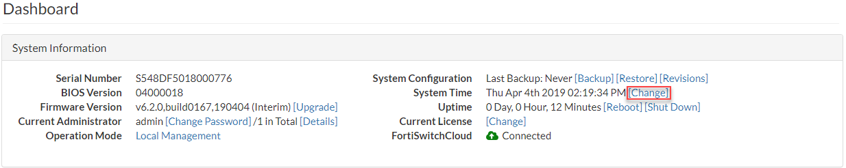
- Go to System > Dashboard.
- Next to the System Time field, select Change.
- Select your Time Zone.
- Either select Manual Setting and enter the system date and time or select Synchronize with NTP Server. If you select synchronization, you can either use the default FortiGuard server or specify a different server. You can also set the Sync Interval.
- Select Update.
If you use an NTP server, you can identify the IPv4 or IPv6 address for this self-originating traffic with the set source-ip or set source-ip6 command. For example, you can set the source IPv4 address of NTP to be on the DMZ1 port with an IP of 192.168.4.5:
config system ntp
set authentication enable
set ntpsyn enable
set syncinterval 5
set source-ip 192.168.4.5
end
Configuring system banners
You can specify system banner messages in the CLI that will appear when users log in using either the CLI or the GUI.
You can enter up to 2,048 characters for each system banner. Currently, only text is supported. By default, no system banners are displayed.
The GUI displays the pre-login banner before you enter your user name or password:

The GUI displays the post-login banner after you enter your user name and password and select Log In:

You cannot finish logging in until you select I Agree.
The CLI displays the pre-login banner before you enter your user name. The CLI displays the post-login banner after you enter your password; you cannot finish logging in until you press a to accept the message.
To configure system banners:
config system global
set pre-login-banner "<string>"
set post-login-banner "<string>"
end
For example:
S548DF5018000776 # config system global
S548DF5018000776 (global) # set pre-login-banner "All systems will be unavailable,
> starting at midnight. Please exit all applications by then."
S548DF5018000776 (global) # set post-login-banner "Remember to exit before midnight."
S548DF5018000776 (global) # end
NOTE: For multi-line messages, just press the Return key between lines.
Configuring the temperature sensor
If your FortiSwitch unit has a temperature sensor, you can set a warning and an alarm for when the system temperature reaches specified temperatures. When these thresholds are exceeded, a log message and SNMP trap are generated. The warning threshold must be lower than the alarm threshold.
Use the following commands to set warning and alarm thresholds:
config system snmp sysinfo
set status enable
set trap-temp-warning-threshold <temperature in degrees Celsius>
set trap-temp-alarm-threshold <temperature in degrees Celsius>
end
By default, the FortiSwitch unit generates an alert (in the form of an SNMP trap and a SYSLOG entry) every 30 minutes when the temperature sensor exceeds its set threshold. You can change this interval with the following commands:
config system global
set alertd-relog enable
set alert-interval <1-1440 minutes>
end
Upgrading the firmware
Use these procedures to upgrade your FortiSwitch firmware.
Using the GUI
You can upgrade the firmware from the dashboard or from the system configuration page.
To upgrade the firmware from the dashboard:
- Go to System > Dashboard.
- Next to the Firmware Version field, select Update.

To upgrade the firmware from the system configuration page:
- Go to System > Config > Firmware.
- Select Choose File and then navigate to the firmware image.

- Select Apply.
Using the CLI
You can download a firmware image from an FTP server, from a FortiManager unit, or from a TFTP server. The FortiSwitch unit reboots and then loads the new firmware.
execute restore image ftp <filename_str> <server_ipv4[:port_int] | server_fqdn[:port_int]>[<username_str> <password_str>]
execute restore image management-station <version_int>
execute restore image tftp <filename_str> <server_ipv4>
The following example shows how to upload a configuration file from a TFTP server to the FortiSwitch unit and restart the FortiSwitch unit with this configuration. The name of the configuration file on the TFTP server is backupconfig. The IP address of the TFTP server is 192.168.1.23.
execute restore config tftp backupconfig 192.168.1.23
You can also load a firmware image from an FTP or TFTP server without restarting the FortiSwitch unit:
execute stage image ftp <string> <ftp server>[:ftp port]
execute stage image tftp <string> <ip>
Verifying image integrity
To verify the integrity of the images in the primary and secondary (if applicable) flash partitions, use the following commands:
execute verify image primary
execute verify image secondary
If the image is corrupted or missing, the command fails with a return code of -1.
For example:
execute verify image primary
Verifying the image in flash......100%
No issue found!
execute verify image secondary
Verifying the image in flash......100%
Bad/corrupted image found in flash!
Command fail. Return code -1
Restore or upgrade the BIOS
You can restore or upgrade the basic input/output system (BIOS) if needed. After a BIOS upgrade, passwords for all FortiSwitch local users must be reconfigured using the config user local setting.
CAUTION: Only restore or upgrade the BIOS if Customer Support recommends it.
To upgrade or restore the BIOS from the CLI:
execute restore bios tftp <filename_str> <server_ipv4[:port_int]>
For example:
execute restore bios tftp PPC/FS-3032D/04000009/FS3D323Z14000004.bin 10.105.2.201
The example downloads the BIOS file from the TFTP server at the specified IPv4 address.
NOTE: If the BIOS upgrade fails, do not restart the FortiSwitch unit. Instead, try the CLI command again. If repeating the CLI command does not work, the FortiSwitch unit might require a return merchandise authorization (RMA).
Setting the boot partition
You can specify the flash partition for the next reboot. The system can use the boot image from either the primary or the secondary flash partition:
execute set-next-reboot <primary | secondary>
NOTE: You must disable image rotation before you can use the execute set-next-reboot command.
If your FortiSwitch model has dual flash memory, you can use the primary and backup partitions for image rotation. By default, this feature is enabled.
config system global
set image-rotation <enable | disable>
end
To list all of the flash partitions:
diagnose sys flash list
Backing up the system configuration
To back up the configuration from the dashboard:
- Go to System > Dashboard.
- Next to the System Configuration field, select Backup.
You can enter a password to encrypt the backup file. Passwords can be up to 15 characters in length.
Remote authentication servers
If you are using remote authentication for administrators or users, you need to configure one of the following:
RADIUS server
The information you need to configure the system to use a RADIUS server includes:
- the RADIUS server’s domain name or IP address
- the RADIUS server’s shared secret key
The default port for RADIUS traffic is 1812. Some RADIUS servers use port 1645. You can configure the FortiSwitch unit to use port 1645:
config system global
set radius-port 1645
end
To configure RADIUS authentication with the GUI:
- Go to System > Authentication > RADIUS and select Add Server.

- Enter the following information and select Add.
|
Field |
Description |
|---|---|
|
Name |
Enter a name to identify the RADIUS server on the FortiSwitch unit. |
|
Primary Server Address |
Enter the domain name (such as fgt.example.com) or the IP address of the RADIUS server. |
|
Primary Server Secret |
Enter the server secret key, such as radiusSecret. This key can be a maximum of 16 characters long. This value must match the secret on the RADIUS primary server. |
|
Secondary Server Name/IP |
Optionally enter the domain name (such as fgt.example.com) or the IP address of the secondary RADIUS server. |
|
Secondary Server Secret |
Optionally, enter the secondary server secret key, such as radiusSecret2. This key can be a maximum of 16 characters long. This value must match the secret on the RADIUS secondary server. |
|
Authentication Scheme |
If you know the RADIUS server uses a specific authentication protocol, select Specify Authentication Protocol and select the protocol from the list. Otherwise, select Use Default Authentication Scheme. The default authentication scheme will usually work. |
|
NAS IP/Called Station ID |
Enter the IP address to be used as an attribute in RADIUS access requests. The NAS IP address is a RADIUS setting or IP address of the FortiSwitch interface used to talk to the RADIUS server, if not configured. The Called Station ID is the same value as the NAS IP address but in text format. |
|
Include in every User Group |
When this option is enabled, this RADIUS server is automatically included in all user groups. This option is useful if all users will be authenticating with the remote RADIUS server. |
To configure the FortiSwitch unit for RADIUS authentication, see 802.1x authentication.
TACACS+ server
TACACS+ is a remote authentication protocol that provides access control for routers, network access servers, and other networked computing devices using one or more centralized servers. TACACS+ allows a client to accept a user name and password and send a query to a TACACS+ authentication server. The server host determines whether to accept or deny the request and sends a response back that allows or denies the user access to the network.
TACACS+ offers fully encrypted packet bodies and supports both IP and AppleTalk protocols. TACACS+ uses TCP port 49, which is seen as more reliable than RADIUS’s UDP protocol.
To configure TACACS+ authentication using the GUI:
- Go to System > Authentication > TACACS and select Add Server.

- Enter the following information and select Add.
|
Field |
Description |
|---|---|
|
Name |
Enter a name to identify the TACACS server on the FortiSwitch unit. |
|
Server Address |
Enter the domain name (such as fgt.example.com) or the IP address of the TACACS server. |
|
Server Key |
Enter the server key for the TACACS server. |
|
Authentication Type |
Select the authentication type to use for the TACACS+ server. Auto tries PAP, MSCHAP, and CHAP (in that order). |
To configure the FortiSwitch unit for TACACS+ authentication, see TACACS.
Configuring system administrators
In addition to the default “admin” account, you might want to set up other administrators with different levels of system access.
This section covers the following topics:
- Administrator profiles
- Creating administrator profiles
- Access control
- Adding administrators
- Monitoring administrators
- Setting the default administrator password
- Setting the password retries and lockout time
- Setting the idle timeout
Administrator profiles
Administer profiles define what the administrator user can do when logged into the FortiSwitch unit. When you set up an administrator user account, you also assign an administrator profile, which dictates what the administrator user will see. Depending on the nature of the administrator’s work, access level, or seniority, you can allow them to view and configure as much, or as little, as required.
The super_admin administrator is the administrative account that the primary administrator should have to log into the FortiSwitch unit. The profile cannot be deleted or modified to ensure there is always a method to administer the FortiSwitch unit. This user profile has access to all components of the system, including the ability to add and remove other system administrators. For some administrative functions, such as backing up and restoring the configuration using SCP, super_admin access is required.
Creating administrator profiles
To configure administrator profiles, go to System > Admin > Profiles. You can only assign one profile to each administrator user.
On the Add Profile page, you define the components of the FortiSwitch unit that will be available to view and/or edit. For example, if you configure a profile so that the administrator can only access System Configuration, this admin will not be able to change Network settings. For more detail about what is covered by each access control, see Access control.
Using the GUI:
- Go to System > Admin > Profiles and select Add Profile.
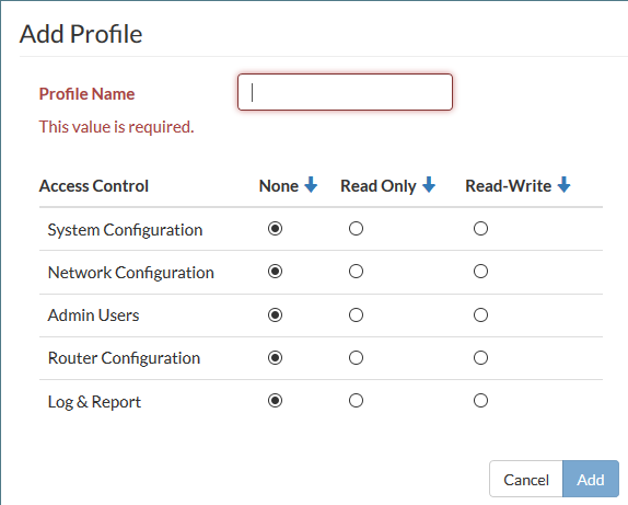
- Give the profile an appropriate name.
- Set Access Control as required, selecting None, Read Only, or Read-Write for each line.
- Select Add.
Using the CLI:
config system accprofile
edit <name>
set admingrp {none | read | read-write}
set loggrp {none | read | read-write}
set netgrp {none | read | read-write}
set routegrp {none | read | read-write}
set sysgrp {none | read | read-write}
end
end
Access control
The System Configuration access control applies to the following menus:
- System > Dashboard
- System > Network > DNS
- System > Network > Settings
- System > Config > SNMP > Communities
- System > Config > SNMP > Users
- System > Config > SNMP > Settings
- System > Config > Firmware
- System > Config > Backup
- System > Config > Revisions
- System > Config > Licenses
- System > Config > Time
- System > Config > SSL
- System > User > Definition
- System > User > Group
- System > Authentication > LDAP
- System > Authentication > RADIUS
- System > Authentication > TACACS
- System > Certificate > Local
- System > Certificate > Remote
- System > Certificate > Authorities
- System > Certificate > CRLs
The Network Configuration access control applies to the follow menus:
- System > Network > Interface > Physical
- System > Network > Interface > VLAN
- System > Network > Interface > Loopback
- Switch > Port > Physical
- Switch > Port > Trunk
- Switch > Interface > Physical
- Switch > Interface > Trunk
- Switch > Interface > Port Security
- Switch > STP > Settings
- Switch > STP > Instances
- Switch > Flap Guard
- Switch > LLDP-MED > Profiles
- Switch > LLDP-MED > Settings
- Switch > POE
- Switch > sFlow
- Switch > Mirror
- Switch > VLAN
- Switch > Virtual Wires
- Switch > Storm Control
- Switch > MAC Entries
- Switch > IP-MAC Binding
- Switch > QoS > 802.1p
- Switch > QoS > IP/DSCP
- Switch > QoS > Egress Policy
- Switch > Monitor > Forwarding Table
- Switch > Monitor > Port Stats
- Switch > Monitor > Spanning Tree
- Switch > Monitor > Modules
- Switch > Monitor > LLDP
- Switch > Monitor > Loop Guard
- Switch > Monitor > Flap Guard
- Switch > Monitor > 802.1x Status
The Admin Users access control applies to the following menus:
- System > Admin > Administrators
- System > Admin > Profiles
- System > Admin > Monitor
- System > Admin > Settings
The Router Configuration access control applies to the following menus:
- Router > Config > OSPF > Settings
- Router > Config > OSPF > Areas
- Router > Config > OSPF > Networks
- Router > Config > OSPF > Interfaces
- Router > Config > RIP > Settings
- Router > Config > RIP > Distances
- Router > Config > RIP > Networks
- Router > Config > RIP > Interfaces
- Router > Config > Static
- Router > Config > Interface
- Router > Config > Link Probes
- Router > Monitor > Routing
- Router > Monitor > Link
The Log & Report access control applies to the follow menus:
- Log > Event Log > Link
- Log > Event Log > POE
- Log > Event Log > Spanning Tree
- Log > Event Log > Switch
- Log > Event Log > Switch Controller
- Log > Event Log > System
- Log > Event Log > Router
- Log > Event Log > User
- Log > Config
Adding administrators
Only the default “admin” account can create a new administrator account. If required, you can add an additional account with read-write access control to add new administrator accounts.
If you log in with an administrator account that does not have the super_admin admin profile, the administrators list will show only the administrators for the current virtual domain.
When adding administrators, you are setting up the administrator’s user account. An administrator account comprises an administrator’s basic settings as well as their access profile. The access profile is a definition of what the administrator is capable of viewing and editing.
Follow one of these procedures to add an administrator.
Using the GUI:
- Go to System > Admin > Administrators.
- Select Add Administrator.
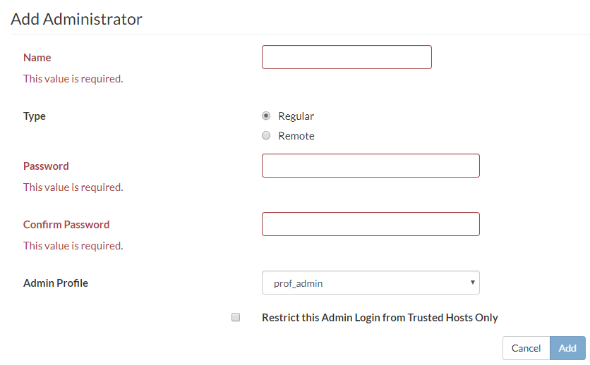
- Enter the administrator name.
- Select the type of account. If you select Remote, the system can reference a RADIUS or TACACS+ server.
- If you selected Remote, select the User Group the account will access, whether wildcards are accepted, and whether the access profile group can be overridden.
- Enter the password for the user. Passwords can be up to 64 characters in length.
- Select Add.
Using the CLI:
config system admin
edit <admin_name>
set password <password>
set accprofile <profile_name>
end
Monitoring administrators
You can find out which administrators are logged in by looking at the System Information section of the Dashboard. The Current Administrator row shows the administrators logged in and the total logged in. Selecting Details displays the information for each administrator: where they are logging in from and how and when they logged in.
Setting the default administrator password
By default, your system has an administrator account set up with the user name admin and no password. On your first login to the GUI or CLI of a new FortiSwitch unit, you must create a password. You are also forced to create a password after resetting the FortiSwitch configuration to the factory default settings with the execute factory reset or execute factoryresetfull command.
To change the default password:
- From the admin menu in the page banner, select Change Password.
- Enter the new password in the Password and Confirm Password fields. Passwords can be up to 64 characters in length.
- Select Change.

Setting the password retries and lockout time
By default, the system includes a set number of three password retries, allowing the administrator a maximum of three attempts to log into their account before they are locked out for a set amount of time (by default, 60 seconds).
The number of attempts can be set to an alternate value, as well as the default wait time before the administrator can try to enter a password again. You can also change this value to make it more difficult to hack. Both settings are must be configured with the CLI
To configure the lockout options:
config system global
set admin-lockout-threshold <failed_attempts>
set admin-lockout-duration <seconds>
end
For example, to set the lockout threshold to one attempt and the duration before the administrator can try again to log in to five minutes, enter these commands:
config system global
set admin-lockout-threshold 1
set admin-lockout-duration 300
end
Setting the idle timeout
By default, the GUI disconnects administrative sessions if no activity occurs for five minutes. This prevents someone from using the GUI if the management PC is left unattended.
To change the idle timeout:
- Go to System > Admin > Settings.
- Enter the time in minutes in the Idle Timeout (Minutes) field.
- Update other settings as required:
- TCP/UDP port values for HTTP, HTTPS, Telnet, SSH
- Display language
- Select Apply.
Configuring administrative logins
You can configure the RADIUS server to set the access profile. This process uses RADIUS vendor-specific attributes (VSAs) passed to the FortiSwitch unit for authorization. The RADIUS access profile override is mainly used for administrative logins.
Using the GUI:
- Go to System > Admin > Administrators.
- Select Add Administrator.
- Select Remote.

- In the Administrator field, enter a name for the RADIUS system administrator.
- Select the user group.
- Select Wildcard.
- Select Accprofile Override.
- Select Add.
Using the CLI:
The following code creates a RADIUS-system admin group with accprofile-override enabled:
config system admin
edit "RADIUS_Admins"
set remote-auth enable
set accprofile no_access
set wildcard enable
set remote-group "RADIUS_Admins"
set accprofile-override enable
next
Ensure that the RADIUS server is configured to send the appropriate VSA.
To send an appropriate group membership and access profile, set VSA 1 and VSA 6, as in the following code:
VENDOR fortinet 12356
ATTRIBUTE Fortinet-Group-Name 1 <admin profile>
ATTRIBUTE Fortinet-Access-Profile 6 <access profile>
The value of VSA 1 must match the remote group, and VSA 6 must match a valid access profile.
Using PKI
You can use Public Key Infrastructure (PKI) to require administrators to provide a valid certificate when logging in with HTTPS.
Use the following steps to configure PKI:
- Configure a peer user.
- Add the peer user to a user group.
- Configure the administrator account.
- Configure the global settings.
To configure a peer user:
config user peer
edit <peer_name>
set ca <name_of_certificate_authority>
next
end
For example:
config user peer
edit pki_peer_1
set ca Fortinet_CA
next
end
To add the peer user to a user group:
config user group
edit <group_name>
set member <peer_name>
next
end
For example:
config user group
edit pki_group_1
set member pki_peer_1
next
end
To configure the administrator account:
config system admin
edit <admin_name>
set peer-auth enable
set peer-group <group_name>
next
end
For example:
config system admin
edit pki_admin_1
set peer-auth enable
set peer-group pki_group_1
next
end
To configure the global settings:
config system gobal
set admin-https-pki-required enable
set clt-cert-req enable
end
Configuring security checks
You can enable various security checks for incoming TCP/UDP packets. The packet is dropped if the system detects the specified condition. Use the appropriate syntax for your FortiSwitch model:
Syntax (for model FS-112D-POE)
config switch security-feature
set tcp-syn-data {enable | disable}
set tcp-udp-port-zero {enable | disable}
set tcp_flag_zero {enable | disable}
set tcp_flag_FUP {enable | disable}
set tcp_flag_SF {enable | disable}
set tcp_flag_SR {enable | disable}
set tcp_frag_ipv4_icmp {enable | disable}
set tcp_arp_mac_mismatch {enable | disable}
|
Variable |
Description |
Default |
|
tcp-syn-data |
TCP SYN packet contains additional data (possible DoS attack). |
disable |
|
tcp-udp-port-zero |
TCP or UDP packet has source or destination port set to zero. |
disable |
|
tcp_flag_zero |
TCP packet with all flags set to zero. |
disable |
|
tcp_flag_FUP |
TCP packet with FIN, URG and PSH flag set. |
disable |
|
tcp_flag_SF |
TCP packet with SYN and FIN flag set. |
disable |
|
tcp_flag_SR |
TCP packet with SYN and RST flag set. |
disable |
|
tcp_frag_ipv4_icmp |
Fragmented ICMPv4 packet. |
disable |
|
tcp_arp_mac_mismatch |
ARP packet with MAC source address mismatch between the layer- 2 header and the ARP packet payload. |
disable |
Syntax (for all other FortiSwitch models)
config switch security-feature
set sip-eq-dip {enable | disable}
set tcp-flag {enable | disable}
set tcp-port-eq {enable | disable}
set tcp-flag-FUP {enable | disable}
set tcp-flag-SF {enable | disable}
set v4-first-frag {enable | disable}
set udp-port-eq {enable | disable}
set tcp-hdr-partial {enable | disable}
set macsa-eq-macda {enable | disable}
|
Variable |
Description |
Default |
|
sip-eq-dip |
TCP packet with source IP equal to destination IP. |
disable |
|
tcp_flag |
DoS attack checking for TCP flags. |
disable |
|
tcp-port-eq |
TCP packet with source and destination TCP port equal. |
disable |
|
tcp-flag-FUP |
TCP packet with FIN, URG, and PSH flags set, and sequence number is zero. |
disable |
|
tcp-flag-SF |
TCP packet with SYN and FIN flag set. |
disable |
|
v4-first-frag |
DoS attack checking for IPv4 first fragment. |
disable |
|
udp-port-eq |
IP packet with source and destination UDP port equal. |
disable |
|
tcp-hdr-partial |
TCP packet with partial header. |
disable |
|
macsa-eq-macda |
Packet with source MAC equal to destination MAC. |
disable |
Logging
FortiSwitchOS provides a robust logging environment that enables you to monitor, store, and report traffic information and FortiSwitch events, including attempted log ins and hardware status. Depending on your requirements, you can log to a number of different hosts.
To configure event logging using the GUI:
- Go to Log > Config.

- Under Event Type, select Enable.
- Under Event Type, select the categories of events that you want logged.
- Select Apply.
To configure event logging using the CLI:
config log eventfilter
set event {enable | disable}
set link {enable | disable}
set poe {enable | disable}
set router {enable | disable}
set spanning_tree {enable | disable}
set switch {enable | disable}
set switch_controller {enable | disable}
set system {enable | disable}
set user {enable | disable}
end
To view the event logs in the GUI:
- Go to Log > Entries.
- From the Subtype dropdown list, select the type of log entries to view.
- From the Level dropdown list, select the severity of events to view.
- From the User dropdown list, select which user or process generated the log entry.
- From the User Interface dropdown list, select the IP network service that applies to the log entry.
- From the Action dropdown list, select the event to view.
- From the Status dropdown list, select the event result to view.
To view the event logs in the CLI:
show log eventfilter
Syslog server
Sysog is an industry standard for collecting log messages for off-site storage. You can send logs to a single syslog server. The syslog server can be configured in the GUI or CLI. Reliable syslog (RFC 6587) can be configured only in the CLI.
To configure a syslog server in the GUI:
- Go to Log > Config.
- Under Syslog, select Enable.
- Select the severity of events to log.
- Enter the IP address or fully qualified domain name in the Server field.
- Enter the port number that the syslog server will use. By default, port 514 is used.
- Select Apply.
To configure a syslog server in the CLI:
config log syslogd setting
set status enable
set server <IP address or FQDN of the syslog server>
set port <port number that the syslog server will use for logging traffic>
set facility <facility used for remote syslog>
set source-ip <source IP address of the syslog server>
end
For example, to set the source IP address of a syslog server to have an IP address of 192.168.4.5:
config log syslogd setting
set status enable
set source-ip 192.168.4.5
end
To configure a reliable syslog server in the CLI:
config log syslogd setting
set status enable
set server <IP address or FQDN of the syslog server>
set mode reliable
set port <port number that the syslog server will use for logging traffic>
set enc-algorithm {high | high-medium | low}
set certificate <certificate_used_to_communicate_with_syslog_server>
end
For example:
config log syslogd setting
set status enable
set source-ip 192.168.4.5
set mode reliable
set port 6514 // This is the default port used for reliable syslog.
set enc-algorithm high-medium
set certificate "155-sub-client"
end
Fault relay support
Fault relays are normally closed relays. When the FSR-112D-POE loses power, the relay contact is in a closed state, and the alarm circuit is triggered.
Using SSH and the Telnet client
Starting in FortiSwitchOS 6.2.0, you can use both IPv4 and IPv6 addresses with SSH and Telnet. If the IPv6 address is a link-local address, you must specify an output interface using %. For example:
execute ssh admin@fe80::926c:acff:fe7b:e059%vlan20 // vlan20 is the output interface.
execute ssh admin@172.20.120.122
execute ssh 1002::21
execute ssh 12.345.6.78
execute telnet fe80::926c:acff:fe7b:e059%vlan20 // vlan20 is the output interface.
execute telnet 1002::21
execute telnet 12.345.6.78