


Example configuration
This example shows the steps for setting up an HA-Cluster using three FortiSandbox units.
Step 1 - Prepare the hardware:
Prepare the following hardware:
- Eleven cables for network connections.
- Four 1/10 Gbps switches.
- Three FortiSandbox units with proper power connections (units A, B, and C). In this example, unit A is the primary node, unit B is the secondary node, and unit C is the worker node.
|
|
Put the primary and secondary nodes on different power circuits. |
Step 2 - Prepare the subnets:
Prepare four subnets for your cluster (customize as needed):
- Switch A: 192.168.1.0/24: For system management.
- Switch B: 192.168.2.0/24: For internal cluster communications.
- Switch C: 192.168.3.0/24: For the outgoing port (port 3) on each unit.
- Gateway address: 192.168.3.1
- Switch D: 192.168.4.0/24: For the file submission port (port 4) on the primary and secondary unit.
Step 3 - Set up the physical connections:
- Connect port 1 of each FortiSandbox device to Switch A.
- Connect port 2 of each FortiSandbox device to Switch B.
- Connect port 3 of each FortiSandbox device to Switch C.
- Connect port 4 of the primary and secondary FortiSandbox device to Switch D.
Step 4 - Configure the primary:
- Power on the device (Unit A), and log into the CLI (see CLI).
- Configure the port IP addresses and gateway address with the following commands:
- Configure the device as the primary node and its cluster failover IP for port1 with the following commands:
- Review the cluster status with the following command:
set port1-ip 192.168.1.99/24
set port2-ip 192.168.2.99/24
set port3-ip 192.168.3.99/24
set port4-ip 192.168.4.99/24
set default-gw 192.168.1.1
hc-settings -sc -tM -nPrimaryA -cTestHCsystem -ppassw0rd -iport2
hc-settings -si -iport1 -a192.168.1.98/24
hc-settings -si –iport4 -a192.168.4.98/24
For information about CLI commands, see the FortiSandbox CLI Reference Guide on the Fortinet Document Library.
hc-status -l
Other ports on the device can be used for file inputs.
Step 5 - Configure the secondary:
- Power on the device (Unit B), and log into the CLI.
- Configure the port IP addresses and gateway address with the following commands:
- Configure the device as the secondary node with the following commands:
- Review the cluster status with the following command:
set port1-ip 192.168.1.100/24
set port2-ip 192.168.2.100/24
set port3-ip 192.168.3.100/24
set port4-ip 192.168.4.100/24
set default-gw 192.168.1.1
hc-settings -sc -tP -nSecondaryB -cTestHCsystem -ppassw0rd -iport2
hc-settings -l
hc-worker -a -s192.168.2.99 -ppassw0rd
hc-status -l
Step 6 - Configure the worker:
- Power on the device (Unit C), and log into the CLI.
- Configure the port IP addresses and gateway address with the following commands:
- Configure the device as a worker node with the following commands:
- Review the cluster status with the following command:
set port1-ip 192.168.1.101/24
set port2-ip 192.168.2.101/24
set port3-ip 192.168.3.101/24
set default-gw 192.168.1.1
hc-settings -sc -tR -cTestHCsystem -ppassw0rd -nWorkerC -iport2
hc-settings -l
hc-worker -a -s192.168.2.99 -ppassw0rd
hc-status -l
Step 7 - Configure client devices to send files to FortiSandbox port4 failover IP:
- Configure client devices to use unit A port4’s failover IP to submit files so that during failover, the new primary node (unit B) port4 will take over that IP.
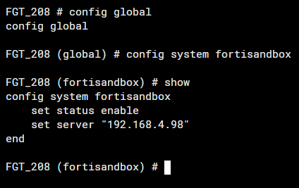
In FortiGate, enable FortiSandbox and connect it to the port4's failover IP.
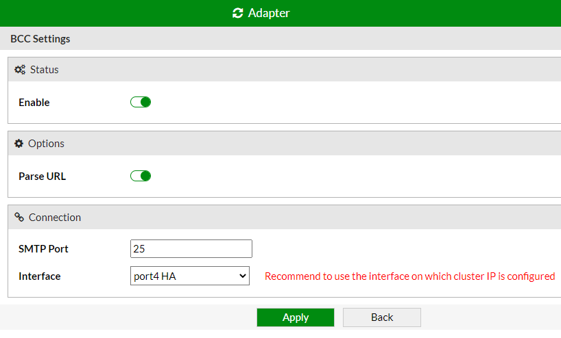
- If you enable adapters such as ICAP, BCC, or MTA on the primary port4’s failover IP, in adapter’s client configuration, you must specify primary port4’s failover IP to make adapter clients send traffic to FortiSandbox HA cluster. The following examples are for BCC and ICAP settings.
-

Step 8 - Configure the following settings on each unit:
- In Scan Policy and Object > VM Settings, set each unit's clone number.
- Configure Network settings such as default gateway, static route, and system DNS.
- In Scan Policy and Object > General Settings set port3 gateway and DNS server.
Scan related settings, such as the scan profile, should be set on primary unit only; they will be synchronized to the worker node. For details, see Primary and worker roles.
Scan input related settings should be set on primary node only as only primary node receives input files.
|
|
If you use the GUI to change a role from worker to standalone, you must remove the worker from the primary using the CLI command |