


FortiGate 3000F and 3001F fast path architecture
The FortiGate 3000F and 3001F each include two NP7 processors (NP#0 and NP#1). All front panel data interfaces (1 to 36) connect to the NP7 processors over the integrated switch fabric. So all supported traffic passing between any two data interfaces can be offloaded.
The FortiGate 3000F and 3001F models feature the following front panel interfaces:
- Two 10 GigE RJ45 (MGMT1 and MGMT2, not connected to the NP7 processors).
- Sixteen 10 GigE RJ45 (1 to 16).
- Sixteen 10/25 GigE SFP+/SFP28 (17 to 30, HA1, and HA2), the HA interfaces are not connected to the NP7 processors.
- Six 40/100 GigE QSFP+/QSFP28 (31 to 26).
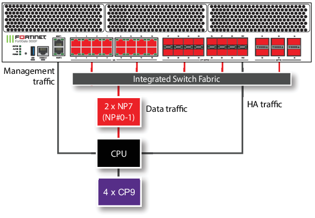
The FortiGate 3000F and 3001F each include two NP7 processors. All front panel data interfaces and the NP7 processors connect to the integrated switch fabric (ISF). All data traffic passes from the data interfaces through the ISF to the NP7 processors. All supported traffic passing between any two data interfaces can be offloaded by the NP7 processors. Data traffic processed by the CPU takes a dedicated data path through the ISF and an NP7 processor to the CPU.
The MGMT interfaces are not connected to the NP7 processors. Management traffic passes to the CPU over a dedicated management path that is separate from the data path. You can also dedicate separate CPU resources for management traffic to further isolate management processing from data processing (see Improving GUI and CLI responsiveness (dedicated management CPU)).
The HA interfaces are also not connected to the NP7 processors. To help provide better HA stability and resiliency, HA traffic uses a dedicated physical control path that provides HA control traffic separation from data traffic processing.
The separation of management and HA traffic from data traffic keeps management and HA traffic from affecting the stability and performance of data traffic processing.
You can use the following command to display the FortiGate 3000F and 3001F NP7 configuration. The command output shows a that all three NP7s are connected to all interfaces.
diagnose npu np7 port-list
Front Panel Port:
Name     Max_speed(Mbps) Dflt_speed(Mbps) NP_group        Switch_id SW_port_id SW_port_name
-------- --------------- ---------------  --------------- --------- ---------- ------------
port1    10000           10000            NP#0-1          0         54
port2    10000           10000            NP#0-1          0         55
port3    10000           10000            NP#0-1          0         52
port4    10000           10000            NP#0-1          0         53
port5    10000           10000            NP#0-1          0         58
port6    10000           10000            NP#0-1          0         64
port7    10000           10000            NP#0-1          0         56
port8    10000           10000            NP#0-1          0         57
port9    10000           10000            NP#0-1          0         66
port10   10000           10000            NP#0-1          0         65
port11   10000           10000            NP#0-1          0         68
port12   10000           10000            NP#0-1          0         67
port13   10000           10000            NP#0-1          0         70
port14   10000           10000            NP#0-1          0         69
port15   10000           10000            NP#0-1          0         72
port16   10000           10000            NP#0-1          0         71
port17   25000           10000            NP#0-1          0         73
port18   25000           10000            NP#0-1          0         74
port19   25000           10000            NP#0-1          0         75
port20   25000           10000            NP#0-1          0         76
port21   25000           10000            NP#0-1          0         35
port22   25000           10000            NP#0-1          0         34
port23   25000           10000            NP#0-1          0         33
port24   25000           10000            NP#0-1          0         32
port25   25000           10000            NP#0-1          0         31
port26   25000           10000            NP#0-1          0         30
port27   25000           10000            NP#0-1          0         29
port28   25000           10000            NP#0-1          0         28
port29   25000           10000            NP#0-1          0         27
port30   25000           10000            NP#0-1          0         26
port31   100000          100000           NP#0-1          0         16
port32   100000          100000           NP#0-1          0         20
port33   100000          100000           NP#0-1          0         8
port34   100000          100000           NP#0-1          0         12
port35   100000          100000           NP#0-1          0         0
port36   100000          100000           NP#0-1          0         4
-------- --------------- ---------------  --------------- --------- ---------- ------------

NP Port:
Name   Switch_id SW_port_id SW_port_name
------ --------- ---------- ------------
np0_0  0         44
np0_1  0         48
np1_0  0         36
np1_1  0         40
------ --------- ---------- ------------
* Max_speed: Maximum speed, Dflt_speed: Default speed
* SW_port_id: Switch port ID, SW_port_name: Switch port name
The command output also shows the maximum and default speeds of each interface.
The integrated switch fabric distributes sessions from the data interfaces to the NP7 processors. The two NP7 processors have a bandwidth capacity of 200Gigabit x 2 = 400 Gigabit. If all interfaces were operating at their maximum bandwidth, the NP7 processors would not be able to offload all the traffic. You can use NPU port mapping to control how sessions are distributed to NP7 processors.
You can add LAGs to improve performance. For details, see Increasing NP7 offloading capacity using link aggregation groups (LAGs).
The FortiGate-3000F and 3001F can be licensed for hyperscale firewall support, see the Hyperscale Firewall Guide.
Configuring NPU port mapping
The default FortiGate-3000F and 3001F port mapping configuration results in sessions passing from front panel data interfaces to the integrated switch fabric. The integrated switch fabric distributes these sessions among the NP7 processors. Each NP7 processor is connected to the switch fabric with a LAG that consists of two 100-Gigabitinterfaces. The integrated switch fabric distributes sessions to the LAGs and each LAG distributes sessions between the two interfaces connected to the NP7 processor.
You can use NPU port mapping to override how data network interface sessions are distributed to each NP7 processor. For example, you can sent up NPU port mapping to send all traffic from a front panel data interface to a specific NP7 processor LAG or even to just one of the interfaces in that LAG.
Use the following command to configure NPU port mapping:
config system npu
config port-npu-map
edit <interface-name>
set npu-group-index <index>
end
<interface-name> the name of a front panel data interface.
<index> select different values of <index> to change how sessions from the selected front panel data interface are handled by the integrated switch fabric. The list of available <index> options depends on the NP7 configuration of your FortGate. For the FortiGate-3000F or 3001F <index> can be:
-
0: NP#0-1, distribute sessions from the front panel data interface among all three NP7 LAGs. -
1: NP#0, send sessions from the front panel data interface to the LAG connected to NP#0. -
2: NP#1, send sessions from the front panel data interface to the LAG connected to NP#1. -
3: NP#0-link0, send sessions from the front panel data interface tonp0_0, which is one of the interfaces connected to NP#0. -
4: NP#0-link1, send sessions from the front panel data interface tonp0_0, which is one of the interfaces connected to NP#0. -
5: NP#1-link0, send sessions from the front panel data interface tonp1_0, which is one of the interfaces connected to NP#1. -
6: NP#1-link1, send sessions from the front panel data interface tonp1_1, which is one of the interfaces connected to NP#1.
For example, use the following syntax to assign the FortiGate-3000F or 3001F port21 and port22 interfaces to NP#0 and port23 and port24 interfaces to NP#1:
config system npu
config port-npu-map
edit port21
set npu-group-index 1
next
edit port22
set npu-group-index 1
next
edit port23
set npu-group-index 2
next
edit port24
set npu-group-index 2
end
end
You can use the diagnose npu np7 port-list command to see the current NPU port map configuration. While the FortiGate-3000F or 3001F is processing traffic, you can use the diagnose npu np7 cgmac-stats <npu-id> command to show how traffic is distributed to the NP7 links.
For example, after making the changes described in the example, the NP_group column of the diagnose npu np7 port-list command output for port21 to port 24 shows the new mapping:
diagnose npu np7 port-list
Front Panel Port:
.
.
.
port21   25000           10000            NP#0            0         35
port22   25000           10000            NP#0            0         34
port23   25000           10000            NP#1            0         33
port24   25000           10000            NP#1            0         32
.
.
.