


FIM-7904E interface module
The FIM-7904E interface module is a hot swappable module that provides data, management, and session sync/heartbeat interfaces, base backplane switching, and fabric backplane session-aware load balancing for a FortiGate-7000 series chassis. The FIM-7904E includes an integrated switch fabric and DP2 processors to load balance millions of data sessions over the chassis fabric backplane to FPM processor modules. The FIM-7904E also includes a 1Gbps base backplane channel for base backplane management communication with each FPM module in the chassis, one 40Gbps fabric backplane channel for fabric backplane communication with the FIM module(s) in the chassis, and a second 1Gbps base backplane channel for base backplane communication with the FIM module(s) in the chassis.
The FIM-7904E can be installed in any FortiGate-7000 series chassis in chassis hub/switch slots 1 or 2. The FIM-7904E provides four Quad Small Form-factor Pluggable plus (QSFP+) interfaces for a FortiGate-7000 chassis. Using a 40GBASE-SR10 multimode QSFP+ transceiver, each QSFP+ interface can also be split into four 10GBASE-SR interfaces.
You can also install FIM-7904Es in a second chassis and operate the chassis in HA mode to provide chassis failover protection.
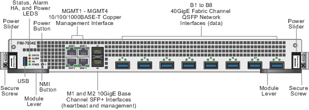
FIM-7904E front panel
Mounting hardware
Use the module levers, power sliders, and secure screws to insert, secure and remove the module from the chassis.
Module levers
Carefully slide the module all of the way into the chassis slot and fully close the module levers to seat the module into the chassis slot and to connect the module to the chassis backplane connectors. When both module levers are fully closed, the power sliders can be lowered to their bottom position, locking the module levers and turning on power to the module.
Raise the power sliders to unlock the module levers and turn off module power. Then open the module levers to eject the module from the backplane connectors; allowing the module to be removed from the chassis.
The module lever mechanism helps reduce the engagement force required to insert or eject the module from the backplane connectors.
The module levers do not fully secure the module in the chassis. The secure screws must be tightened to reliably secure the module in the chassis and to make sure the module remains securely connected to the backplane for power and network connectivity.
Power sliders
Close the module levers and move the power sliders to their bottom position to lock the module levers and turn the module power switch on.
Move the power sliders to the top position to unlock the module levers and turn the module power switch off.
Gently push the power sliders down to make sure they are in their bottom position. If the module LEDs do not light the module is not receiving power. If this happens check the power sliders to make sure they are in their bottom position.
Secure screws
Fully tighten the secure screws to lock the module in the chassis providing a secure and reliable connection with the backplane.
Loosen the secure screws before ejecting the module from the chassis.
Front panel interfaces
You connect the FIM-7904E to your 40Gbps networks using the B1 to B8 front panel QSFP+ interfaces. The front panel also includes M1 and M2 SFP+ interfaces for the base channel, four Ethernet management interfaces (MGMT1 to MGMT4), and a USB port. The USB port can be used with any USB key for backing up and restoring configuration files.
| Connector | Type | Speed | Protocol | Description |
|---|---|---|---|---|
| B1 to B8 | QSFP+ | 40Gbps/10Gbps | Ethernet | Eight front panel 40GigE QSFP+ fabric channel interfaces. These interfaces are connected to 40Gbps networks to distribute sessions to the FPM processor modules installed in chassis slots 3 and up. Using 40GBASE-SR10 multimode QSFP+ transceivers, each QSFP+ interface can also be split into four 10GBASE-SR interfaces. These interfaces also support creating link aggregation groups (LAGs) that can include interfaces from both FIM-7904Es. |
| M1 and M2 | SFP+ | 10Gbps/1Gbps | Ethernet | Two front panel 10GigE SFP+ interfaces that connect to the base backplane channel. These interfaces are used for heartbeat, session sync, and management communication between FIM-7904Es in different chassis. These interfaces can also be configured to operate as Gigabit Ethernet interfaces using SFP transceivers, but should not normally be changed. If you use switches to connect these interfaces, the switch ports should be able to accept packets with a maximum frame size of at least 1526. The M1 and M2 interfaces need to be on different broadcast domains. If M1 and M2 are connected to the same switch, Q-in-Q must be enabled on the switch |
| MGMT1 to MGMT4 | RJ-45 | 10/100/1000Mbps | Ethernet | Four 10/100/1000BASE-T copper out of band management Ethernet interfaces. |
| USB | USB 3.0 Type A | USB 3.0 USB 2.0 | Standard USB connector. |
Physical description
| Dimensions | 1.88 x 17.11 x 18.49 in. (48 x 435 x 470 mm) (Height x Width x Length) |
| Weight | 16.0 lb. (7.3 kg) |
| Operating Temperature | 32 to 104°F (0 to 40°C) |
| Storage Temperature | -31 to 158°F (-35 to 70°C) |
| Relative Humidity | 10% to 90% (Non-condensing) |
| Power consumption | Max: 450W; Average: 400W |
| Max Current | 37.5A |
| Heat Dissipation | 1531BTU/h |
| Joules/h | 1609KJ/h |
Front panel LEDs
From the FIM-7904E font panel you can view the status of the module LEDs to verify that the module is functioning normally.
| LED | State | Description |
|---|---|---|
| STATUS | Off | The FIM-7904E is powered off. |
| Green | The FIM-7904E is powered on and operating normally. | |
| Flashing Green | The FIM-7904E is starting up. | |
| ALARM | Red | Major alarm. |
| Amber | Minor alarm | |
| Off | No alarms | |
|
HA |
Off | The FIM-7904E is operating in normal mode. |
| Green | The FIM-7904E is operating in HA mode. | |
| Red | A failover has occurred | |
| POWER | Green | The FIM-7904E is powered on and operating normally. |
| Off | The FIM-7904E is powered off. | |
| B1 to B8 | Green | The correct cable is connected to the interface and the connected equipment has power and is connected at 40Gbps or 10Gbps. If the port is split the LED will light as long as at least one of the 10 Gbps connections is active. |
| Flashing Green | 40 Gbps or 10Gbps network activity at the interface. | |
| Off | No link is established. | |
| M1 and M2 | Green | The correct cable is connected to the interface and the connected equipment has power. |
| Flashing Green | Network activity at the interface. | |
| Off | No link is established. | |
| MGMT1-4 Link/Act | Solid Green | Indicates this interface is connected with the correct cable and the attached network device has power. |
| Blinking Green | Indicates network traffic on this interface. | |
| Off | No Link | |
|
MGMT1-4 Speed |
Green | Connection at 1Gbps. |
| Amber | Connection at 100Mbps. | |
| Off | Connection at 10Mbps. | |
Supported transceivers and breakout cables
Transceivers available from Fortinet for the FIM-7904E B1 to B8 QSFP+ interfaces.
| Transceiver | Description |
|---|---|
| FG-TRAN-QSFP+SR | 40GE QSFP+ transceivers, short range. |
| FG-TRAN-QSFP+LR | 40GE QSFP+ transceivers, long range. |
Breakout cables available from Fortinet for the FIM-7904E B1 to B8 QSFP+ interfaces.
| Breakout | Description |
|---|---|
| FG-TRAN-QSFP-4XSFP | 40GE QSFP+ Parallel Breakout Active Optical Cable with 1m length. |
| FG-TRAN-QSFP-4SFP-5 | 40GE QSFP+ Parallel Breakout MPO to 4x LC connectors, 5m reach. |
Splitting the FIM-7904E B1 to B8 interfaces
Each 40GE interface (B1 to B8) on the FIM-7904Es in slot 1 and slot 2 of a FortiGate-7000 system can be split into 4x10GBE interfaces. You split these interfaces after the FIM-7904Es are installed in your FortiGate-7000 system and the system us up and running. You can split the interfaces of the FIM-7904Es in slot 1 and slot 2 at the same time by entering a single CLI command. Enabling, disabling, or changing the split interfaces configuration requires a system reboot. Fortinet recommends that you split multiple interfaces at the same time according to your requirements to avoid traffic disruption.
For example, to split the B1 interface of the FIM-7904E in slot 1 (this interface is named 1-B1) and the B1 and B4 interfaces of the FIM-7904E in slot 2 (these interfaces are named 2-B1 and 2-B4) connect to the CLI of your FortiGate-7000 system using the management IP and enter the following command:
config system global
set split-port 1-B1 2-B1 2-B4
end
After you enter the command, the FortiGate-7000 reboots and when it comes up:
- The 1-B1 interface will no longer be available. Instead the 1-B1/1, 1-B1/2, 1-B1/3, and 1-B1/4 interfaces will be available.
- The 2-B1 interface will no longer be available. Instead the 2-B1/1, 2-B1/2, 2-B1/3, and 2-B1/4 interfaces will be available.
- The 2-B4 interface will no longer be available. Instead the 2-B4/1, 2-B4/2, 2-B4/3, and 2-B4/4 interfaces will be available.
You can now connect breakout cables to these interfaces and configure traffic between them just like any other FortiGate interface.
Turning the FIM-7904E on and off
You can use the front panel power button to turn the FIM-7904E power on or off. If the FIM-7904E is powered on, press the power switch to turn it off. If the FIM-7904E is turned off and installed in a chassis slot, press the power button to turn it on.
NMI switch
When working with Fortinet Support to troubleshoot problems with the FIM-7904E you can use the front panel non-maskable interrupt (NMI) switch to assist with troubleshooting. Pressing this switch causes the software to dump registers/backtraces to the console. After the data is dumped the FIM-7904E reboots. While the FIM-7904E is rebooting, traffic is temporarily blocked. The FIM-7904E should restart normally and traffic can resume once the it is up and running.
FIM-7904E hardware architecture
The FIM-7904E includes an integrated switch fabric (ISF) that connects the front panel interfaces to the DP2 session-aware load balancers and to the chassis backplanes. The ISF also allows the DP2 processors to distribute sessions among all NP6 processors on the FPM modules in the same chassis.
The FIM-7904E also includes the following backplane communication channels:
- One 80Gbps fabric backplane channel to distribute traffic to the FPMs.
- One 1Gbps base backplane channel for base backplane communication with the FPMs.
- One 40Gbps fabric backplane channel for fabric backplane communication with the other FIM.
- One 1Gbps base backplane channel for base backplane communication with the other FIM.
FIM-7904E hardware architecture
