


Scenario 1 – Layer 2 Transparent Proxy
This is the most common deployment type, the client and FortiADC are on the same subnet. They don’t need to have IP address changed. This topology is also known as a stealth firewall.
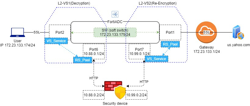
Topology
Creating a Soft-switch
- Go to Network > Interface, then click the tab Interface.
- Click Create New to display the configuration editor.
- Complete the key configuration as shown in the screenshot.
- Name: Enter a unique name for the soft-swtich name
- Type: Select the Softswtich
- Member in Type Specifics: Bind the ports facing the client side and gateway side. In the above topology, that is Port1 and Port2.
- IPv4 in Mode Specifics: Type the address of the softswitch. In the above topology, that is 172.23.133.175/24.
- Save the configuration.

Creating Client SSL Profile for SSLi instance
- Go to SSLi Proxy > Application Resources, then click the tab Client SSL.
- Click Create New > Advanced Mode to display the configuration editor.
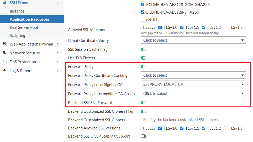
- Complete the key configuration as shown in the screenshot.
- Name: Enter a unique name for the SSLi instance name.
- Forward Proxy: Enable this option.
- Forward Proxy Local Signing CA: Select a CA certificate that your client trusts it.
- Backend SSL SNI Forward: Enable this option.
- Save the configuration.
Creating Real Server Profile for SSLi instance
- Go to SSLi Proxy > Real Server Pool, then click the tab Real Server.
- Click Create New to display the configuration editor.
- Complete the key configuration as shown in the screenshot. Here we need to add two real servers, one connecting with the gateway, and the other connecting with the security device.
- Name: Enter a unique name for the Real Server.
- Address: Enter the correct IP address.
- Save the configuration.
- Go to SSLi Proxy > Real Server Pool, then click the tab Real Server Pool. Here we need to create two real server pools containing the above two real servers respectively.
- Click Create New to display the configuration editor.
- Complete the key configuration as shown in the screenshot.
- Name: Enter a unique name for the Real Server Pool.
- Real Server SSL Profile: Enable SSL on the real server to the gateway side, and disable SSL on the one to the security device side.
- Member: Select the correct the real server in your topology.
- Save the configuration.


Configuring Static Routing
- Go to Network > Routing, then click the tab Static.
- Click Create New to display the configuration editor.
- Complete the key configuration as shown in the screenshot.
- Destination: Enter a Client IP address scope.
- Gateway: Enter a Security Device IP address which in the Re-encryption side.
- Save the configuration.
This static routing forwards the packets whose destination is the client IP to the security device.

Creating SSLi instance for L2 deploy
- Go to SSLi Proxy > Instance, then click the tab Instance.
- Click Create New > Advanced Mode to display the configuration editor.
- Complete the key configuration as shown in the screenshot.
- Name: Enter a unique name for the SSLi instance.
- Topology: Select the L2 Transparent Proxy.
- Decryption tab
- Inbound Interface: Select the Softswitch type interface you just created.
- Client SSL Profile: Select the client SSL profile you just created.
- Outbound Real Server Pool: Select the server pool to the security device.
- Re-encryption tab
- Inbound Interface: Select an interface connected to the security device side.
- Outbound Real Server Pool: Select the server pool to the gateway side.
- Onbound Interface Status: Enable this option.
- Onbound Interface: Select the interface connected to the gateway side.
If you have configured both L7 and L2/L3 instances for the same security device (attached to the same subnets), their port numbers must not be the same. We will remove this restriction in later releases.
- Save the configuration.

Enabling rt-cache-strict
Run the following command:
config router setting
set rt-cache-strict enable
config rt-cache-reverse-exception
end
end
Client side: install CA and try the SSLi function
- Install the Local Signing CA that FortiADC selected.
- Open the browser and navigate to https://us.yahoo.com, you will see the derived certificate is signed by "Local Signing CA".

Testing SSLi deployment
To test the deployment, check if the plain HTTP traffic is logged on the security device.
