


Server load balance layer 4
Server Load Balance overview
FortiADC is like an advanced server load balancer. It can balance traffic to available destination servers based on health checks and load-balancing algorithms.
The physical distance between clients and the servers in your backend server—and other factors, like the number of simultaneous connections that the servers can handle, or load distribution among the servers -- are important contributing factors to server performance. So the purpose of FortiADC is to give user multiple methods for optimizing server response times and server capacity. Traffic is routed to the FortiADC virtual server instead of the destination real servers.
For layer 4 virtual server, it has five packet forwarding methods—Direct Routing, DNAT, Full NAT, Tunneling, NAT46.
Server Load Balance Layer-4 VS
Direct Routing mode
Direct Routing mode works by changing the destination MAC address of the incoming packet to match the selected Real Server. DR mode is transparent. The Real Server will see the source IP address of the client.
Topology:

GUI:

- When the packet reaches the Real Server, it expects the Real Server to own the VS IP. This means that you need to ensure that the Real Server (and the load balanced application) respond to both the Real Servers own IP address and the VS IP.
- FortiADC must have an interface in the same subnet as the Real Servers to ensure layer2 connectivity required for DR mode to work.
- The VIP can be brought up on the same subnet as the Real Servers, or on a different subnet provided that the load balancer has an interface in that subnet
- Port translation is not possible in DR mode i.e. having a different RIP port than the VIP port
DR mode for Windows server
Add a loopback adapter, set the virtual-server IP to the loopback adapter.
- Click Start, then type cmd in the search box.
- When cmd.exe appears, right-click it and choose Run as administrator.
- In the command prompt, type hdwwiz.exe and press Enter.
- Click Next.
- Select Install the hardware that is manually selected from a list (Advanced), then click Next.
- Select Network adapters, then click Next.
- Select Microsoft as the manufacturer, select Microsoft KM-TEST Loopback Adapter as the adapter for Windows 10, then click Next.
- Select Next to confirm the installation.
- Select Finish to complete the installation.
- Find the new added loopback adapter, then set the virtual-server IP to the loopback adapter.
Rename the name of NIC connecting to FortiADC to new name, such as “nic_to_adc”, rename the new added loopback NIC to “loopback”, then execute the following command:
netsh interface ipv4 set interface "nic_to_adc" weakhostreceive=enabled
netsh interface ipv4 set interface "loopback" weakhostreceive=enabled
netsh interface ipv4 set interface "loopback" weakhostsend=enabled
DNAT mode
Typically, Layer 4 DNAT uses two interfaces connecting to client and real servers. The packet’s destination IP will be changed after going through the FortiADC VS.
Topology:

GUI:

- Use DNAT as the packet forwarding method and set the default gateway on each server to FortiADC’s IP address on the same subnet/VLAN (or, use static routes to send responses to FortiADC’s IP address)
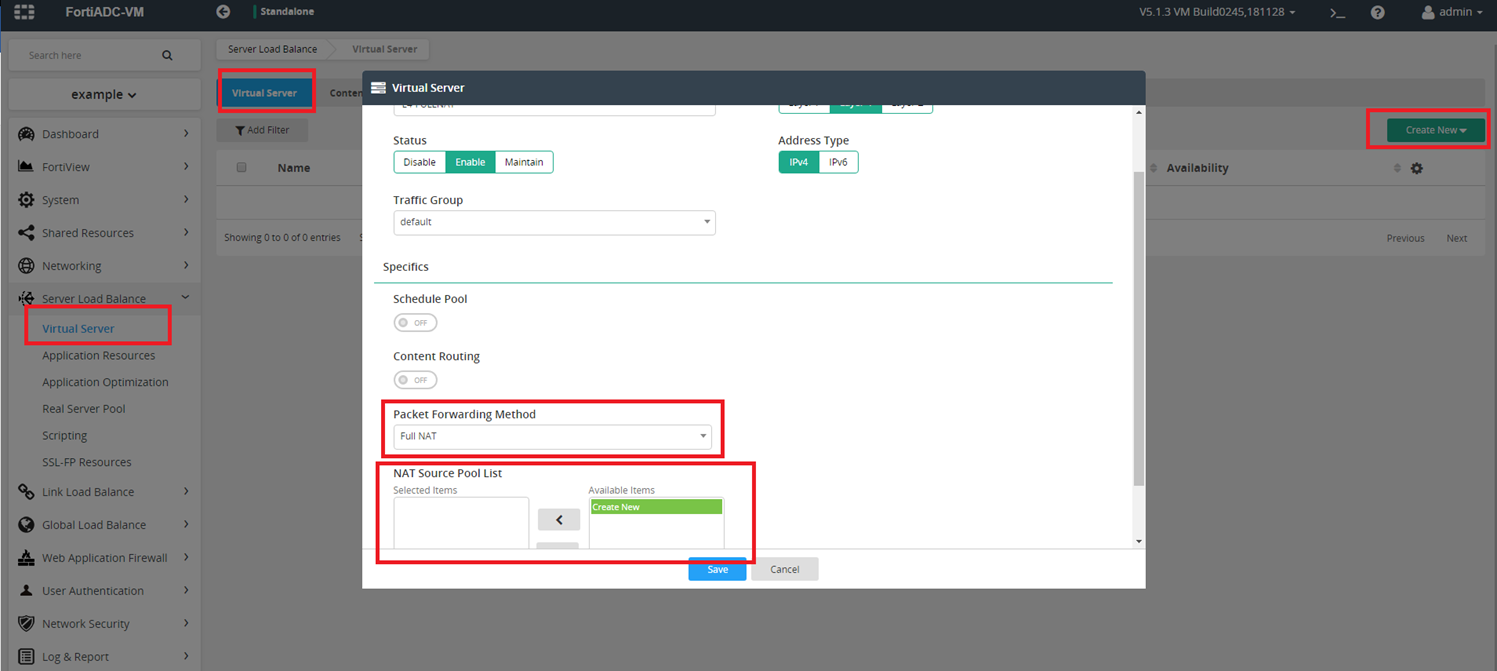
FULLNAT mode
Layer 4 FULLNAT VS changes the packet’s source and destination address before sending the packet to real servers. User can self-define the pool IP address range in the NAT source pool, and select it in Pool List. Normally, the NAT source pool’s address range is in the same network subnet with real server.
Topology:

GUI:
Tunneling mode
Tunneling mode VS is based on direct routing mode. The FortiADC VS encapsulates the original packet (client IP to Virtual Server IP) inside an ipip packet of ADC IP to real server IP, which is put into an output chain and is routed to the real server. The real server receives the packet on a tunl0 device and decapsulates the ipip packet, revealing the original packet (client IP to Virtual Server IP). Then it sends the packet to client.
Topology:

GUI:

NAT46 mode
NAT46 mode VS converts the packet’s source address from ipv4 to ipv6, which were set in NAT source pool. Then it sends them to ipv6 real server.
Topology:

GUI:

FortiADC SLB4 Deployment with FullNAT mode and TCP profile and WRR method
SLB4 FullNAT Example Topology

SLB4 FullNAT, TCP profile, WRR method steps

To deploy a SLB Layer 4 server:
Step 1: Create new Real Server

Step 2: Create new Real Server Pool and add real servers into it.


Step 3: Create a NAT source Pool

Step 4: Create FullNAT Virtual Server and choose Real Server Pool


Step 5: Choose Profile TCP and Method LB_METHOD_ROUND_ROBIN

Set real server’s weight (optional)
|
|
If you want to set different weights to the real server, please change the weight in Real Server Pool. For example: RealServer1’s weight is 1, RealServer2’s weight is 2. The total connections are 30, in this condition, 10 connections go to RealServer1, and another 20 connections go to RealServer2. |


Step 6: Send traffic from client using tools like “curl” or “wget”


Check if the WRR method works. If you send three requests to the virtual server, you should receive two responses for real server 2, and one response for real server 1.

Check traffic log and session table information
• Check the traffic log:
We need to enable traffic log in virtual server and Log&Report.


Check if WRR method works as expected from the traffic log:
From the traffic log, we can see the traffic go to the real server according to their weight (RS1:RS2=1:2).

• Check the session table:
Fortiview

CLI
