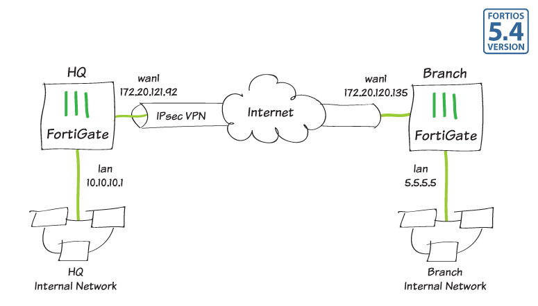
Site-to-site IPsec VPN with two FortiGates
In this example, you will allow transparent communication between two networks that are located behind different FortiGates at different offices using route-based IPsec VPN. The VPN will be created on both FortiGates by using the VPN Wizard's Site to Site - FortiGate template.
In this example, one office will be referred to as HQ and the other will be referred to as Branch.
1. Configuring the HQ IPsec VPN
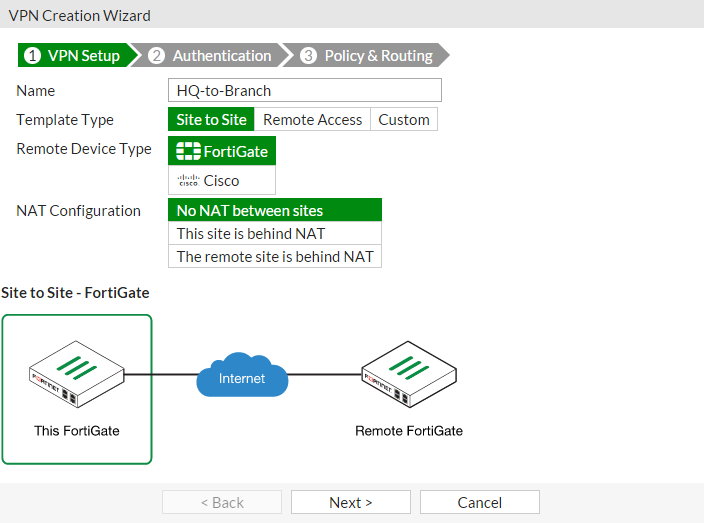
On the HQ FortiGate, go to VPN > IPsec Wizard.
Select the Site to Site template, and select FortiGate.
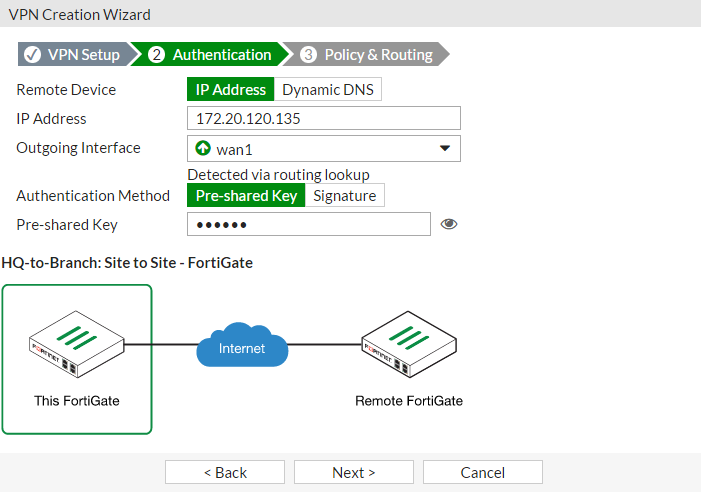
In the Authentication step, set IP Address to the IP of the Branch FortiGate (in the example, 172.20.120.135). After you enter the gateway, an available interface will be assigned as the Outgoing Interface. If you wish to use a different interface, select it from the drop-down menu.
Set a secure Pre-shared Key.
In the Policy & Routing step, set the Local Interface. The Local Subnets will be added automatically. Set Remote Subnets to the Branch FortiGate's local subnet (in the example, 5.5.5.5/24).

A summary page shows the configuration created by the wizard, including firewall addresses, firewall address groups, a static route, and security policies.

2. Configuring the Branch IPsec VPN
On the Branch FortiGate, go to VPN > IPsec Wizard.
Select the Site to Site template, and select FortiGate.

In the Authentication step, set IP Address to the IP of the HQ FortiGate (in the example, 172.20.121.92). After you enter the gateway, an available interface will be assigned as the Outgoing Interface. If you wish to use a different interface, select Change.
Set the same Pre-shared Key that was used for HQ's VPN.

In the Policy & Routing step, set the Local Interface. The Local Subnets will be added automatically. Set Remote Subnets to the HQ FortiGate's local subnet (in the example, 10.10.10.1/24).

A summary page shows the configuration created by the wizard, including firewall addresses, firewall address groups, a static route, and security policies.

3. Results
On either FortiGate, go to Monitor > IPsec Monitor to verify the status of the VPN tunnel. Right-click under Status and select BringUp.

A user on either of the office networks should be able to connect to any address on the other office network transparently.
If you need to generate traffic to test the connection, ping the Branch FortiGate's internal interface from the HQ's internal network.